
Table of contents: Installing the front panel in the… ↓ Removal and installation the front… ↓
1. Front panel installation details are shown in the illustration.
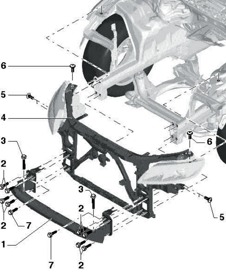
2.1. Front panel installation details:
1 - Front bumper beam: to remove the beam, unscrew bolts 3, and to remove the shock absorbers, unscrew bolts 2 and 7;
2 - Bolt, 60 Nm;
3 - Bolt, 22 Nm;
4 - Front panel;
5 - Bolt 3 Nm;
6 - Bolt, 25 Nm.
Installing the front panel in the service position
Note: When installing the front panel in the service position, the refrigerant, coolant and power steering fluid lines, as well as the electrical wiring connectors, are not disconnected.
2. Disconnect the negative battery cable (see Chapter 5).
3. Remove the front bumper cover (see Section 9).
4. Separate the front wheel arch liners at the mounting areas on the bumper.
5. Remove the sound insulation panels under the engine compartment (see Section 19 of Chapter 1).
6. Remove the seal from the front panel and from its connections to the wings.
7. Remove the headlights (see Chapter 11).
8. Disconnect the hood release cable at the connection point (see Section 4).
9. Separate the intercooler pressure hoses (see Chapter 4).
10. Remove the bolts (4 and 3 in the illustration) and bolts (2) on the top right and top left on the side member.
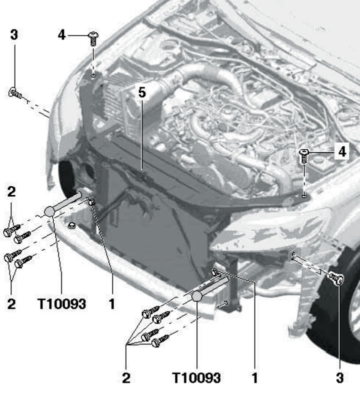
2.10. Installing the front panel in the service position:
1 - Bolt, 6 Nm: do not unscrew to install panel 5 in the service position;
2 - Bolt, 60 Nm, replaceable with guide pin T10093;
3 - Bolt, 3 Nm;
4 - Bolt, 25 Nm;
5 - Front panel.
Screw the T10093 guide pins into the released threaded holes, then unscrew the remaining bolts (2) and pull the front panel forward on the guide pins by approximately 10 cm, avoiding excessive tension on the electrical wiring.
11. Installing the front panel to its original position is done in reverse order. Do not pinch the electrical wiring. After installation, adjust the headlights (see Chapter 11).
Removal and installation the front panel
12. Follow the steps in paragraphs 2-9.
13. Remove the bolts (4 and 3 in the illustration) and bolts (2). Remove the front panel.
14. Install the front panel in reverse order. Do not pinch the electrical wiring. After installation, adjust the headlights (see Chapter 11).