
Table of contents: Specifications ↓ Gaps between body elements, mm ↓ Control body dimensions, mm ↓ General information ↓ Parts secured with adhesive tape ↓
Specifications
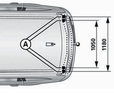
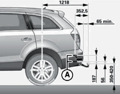
Attachment points (A) for towing hitch for aftermarket installation, mm.
Gaps between body elements, mm
Note: To measure gaps between body elements, use control plate set No. 3371.
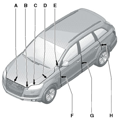
Gaps in the front and center of the body:
A, B, G, H - 4.5;
C - 5.0;
D - 3.0;
E - 2.5;
F - 3.5.
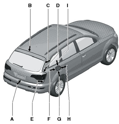
Rear body clearances, mm:
A - 5.0;
B, C, E - 4.5;
D - 5.5;
F-I - 2.0.
Control body dimensions, mm
Note: All dimensions are for checking purposes only; the correct dimensions are set by the frame. Tolerances for all dimensions are ±2 mm.
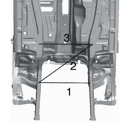
Dimensions of the bottom, front, mm:
1 - 882 (between the front mounting points of the front suspension);
2 - 1150 (diagonally between the front suspension mounting points);
3 - 880 (between the rear mounting points of the front suspension).
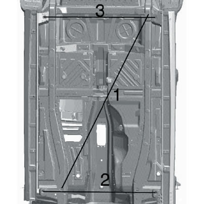
Bottom dimensions, center, mm:
1 -2175 (diagonally between the front and rear suspension mounting points);
2 - 1312 (between the front mounting holes);
3 - 1295 (between the front mounting points of the rear suspension).
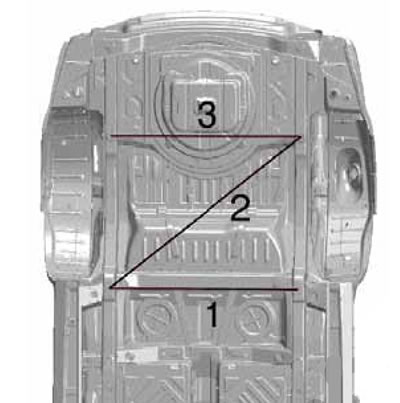
Bottom dimensions, rear mm:
1 - 1115 (between the front mounting points of the front suspension);
2 - 1400 (diagonally between the front suspension mounting points);
3 - 1115 (between the rear mounting points of the front suspension).
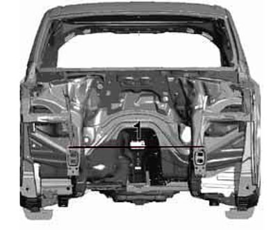
Dimensions of the front part of the body, part 1 of 2, mm.
1 - 1000 (between the front side members).
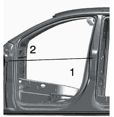
Dimensions in the central part of the body, part 1 of 2, mm:
1 - 1178 (between the hinges of the front and rear doors);
2 - 1549 (between the A-pillars).
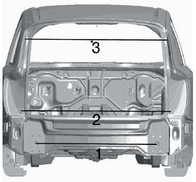
Changes in the rear of the body, mm:
1 - 1115 (between the rear side members);
2 - 1383 (between the rear light supports);
3 - 1310 (between the mounting points of the rear door pillars).
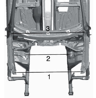
Dimensions of the front part of the body, part 2 of 2, mm:
1 - 1430 (between the wing fasteners);
2 - 943 (between the attachment points of the shock absorber supports);
3 - 1546 (between the wings at the back).
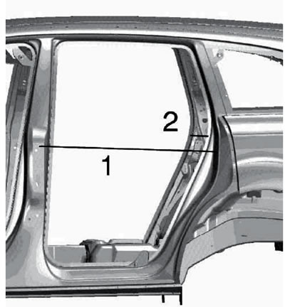
Dimensions in the central part of the body, part 2 of 2, mm:
1 - 965 (between pillars B and C);
2 - 1497 (between the C-pillars).
General information
This chapter covers repair and removal/installation procedures for the most frequently serviced components. Procedures related to welding operations are not considered. Removal/installation of some trim elements secured with double-sided adhesive tape or fasteners (decorative trims, seals, moldings, spoilers, etc.), is not considered due to the typical nature of these works - only illustrations are given to explain the details of installing such elements. For the same reason, procedures for replacing glued-in glass are not considered (instructions are included with the glass gluing repair kit).
Parts secured with adhesive tape
To remove a part secured with adhesive tape, carefully lift its edge and, cutting the adhesive tape with a knife, continue to pull the part away. To soften the adhesive layer, you can use a hair dryer.
After removal, clean the part and its mounting surface from any remaining adhesive tape and degrease the surfaces.
To install, remove the protective film from the adhesive tape and press the part.
Please observe the following notes:
- Apply the adhesive at ambient and object temperatures between 18 and 25°C;
- Freshly painted parts can be pasted over only after the drying time has elapsed (at least 24 hours);
- Optimal bonding with the base is achieved after approximately 48 hours; prior to this, parts should not be subjected to mechanical stress (car wash, strength testing, etc.);
- Do not touch the sticking surface;
- For gluing, it is not the duration that is important, but the pressing force;
- Removal the adhesive tape immediately after pressing may destroy the adhesive layer;
- By applying light pressure, the adhesive tape can be peeled off and reapplied up to 3 times.
[The article was copied from the website: AUDImanual.ru]