
Table of contents: Checking the proper installation of… ↓ All ↓ All ↓ All ↓ All ↓ Tightening torques (Nm) ↓ Drive shaft heat shield tightening… ↓ Dual-clutch transmission for 2.0L… ↓ Dual-clutch transmission for 3.2L… ↓ Dual-clutch transmission for 2.0L… ↓ Dual-clutch transmission for 3.0L… ↓
Note: Replace bolts that have been tightened to the limit. Replace self-locking nuts and bolts, as well as sealing rings, gaskets and sealing cuffs. Hose nipples, as well as air duct tubes and hoses of the air booster system, must be cleaned of oil and grease before installation. Secure all hose connections with hose clamps of the appropriate standard. In order to securely fasten the air ducts in the nipples, the screw spirals in the hose clamps already in use must be sprayed with a corrosion solvent before installation. During installation, reinstall all binders in their places.
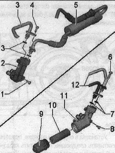
There are 2 different versions of the ATF filter, depending on the design and engine. Remove the ATF "5" main filter and the ATF "10" replaceable filter. The ATF "10" replaceable filter must be replaced with each ATF change or when repairing the gearbox. The ATF "5" main filter must be replaced when replacing the gearbox or if the ATF is heavily contaminated. Risk of damage to parts. When replacing a gearbox with an ATF "5" main filter with a gearbox with an ATF "10" replaceable filter, the ATF supply and return lines must be replaced. The ATF lines are NOT the same. Failure to replace the ATF lines will result in leaks and damage to the ATF lines. The ATF "10" replaceable filter must be replaced with each ATF change in the future. Make the appropriate entries in the vehicle specifications and repair history. Due to certain circumstances, the replacement of the ATF automatic replaceable filter is not displayed in the maintenance tables. If a gearbox with a replaceable ATF filter is installed, it is necessary to ensure that a hose breather is installed.
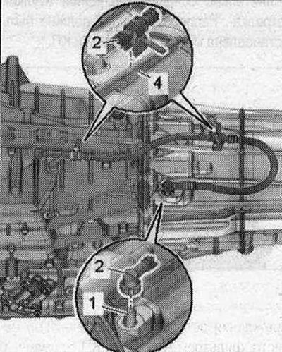
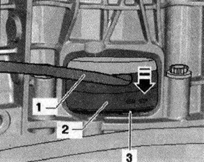
Checking the proper installation of the breather hose - vehicles with a gearbox with a replaceable ATF filter
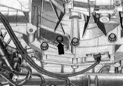
The elbow of the hose breather "2" must be placed on the connecting nipple "1". Press the loose elbow until it locks. Check the correct fit of the clamping base "4": the distance from the rear clamping base to the housing flange must be 130 mm. The ATF breather "3" must remain free.
All
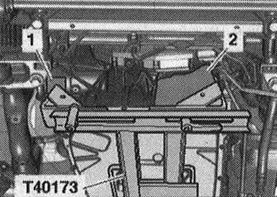
After replacing the gearbox or after repairing the gearbox, clean the ATF lines and cooler. Before installing the gearbox, be sure to clean the threaded holes connecting the engine and gearbox in the cylinder block using a tap. Risk of depressurization of the ATF pan. Do not touch the ATF pan with the gearbox support "T40173". Install a powertrain lift with a prepared gearbox mount "T40173" under the gearbox. From the front, the gearbox mount must be installed as follows: on the left side, the mounting block "2" goes into the hole for the flywheel on the gearbox housing; on the right side of the gearbox, the elastic gearbox mounting gasket "1" touches the central differential housing.
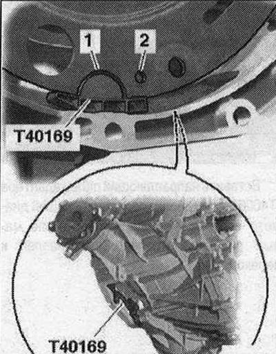
Secure the gearbox using tension belt "1". Before connecting the engine and gearbox, perform the following preparatory actions. Install auxiliary mounting device "T40169" from below in the gearbox housing and in the clutch module, as shown in the figure. The mounting device must fit into the semicircular groove "1" and additionally into the inspection hole "2". There is one inspection hole along the perimeter, accordingly turn the clutch module. Insert the mounting device bolts into the hole on the gearbox housing.
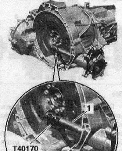
Install the "T40170" transport protection from below under the gearbox housing and attach it to the shaft with flange "1". Check the aluminum engine-gearbox connection bolts for reuse and, if necessary, mark them.
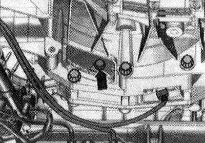
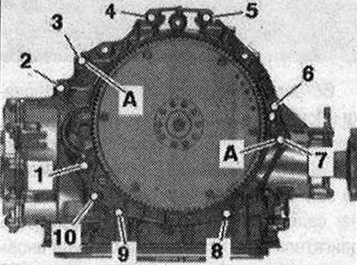
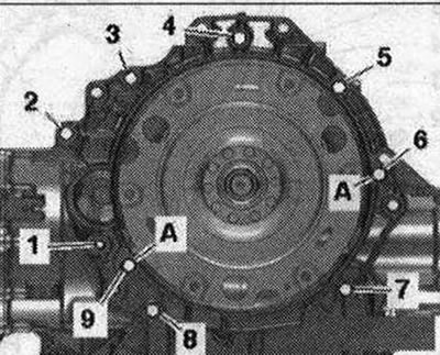
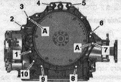
Vehicles with 2.0 l TFSI engine: Check the presence of centering bushings "A" of the engine and gearbox in the cylinder block; insert the bushings if necessary. Place the engine on the gearbox and tighten bolts "6" and "7" of the engine/gearbox connection.
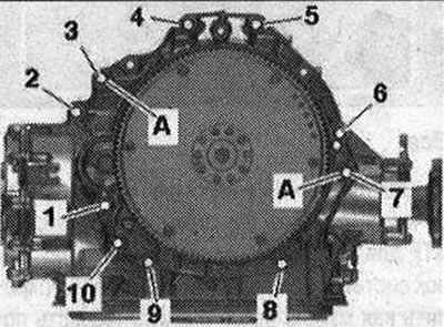
Vehicles with 2.0 l TDI engine: Check the presence of centering bushings "A" of the engine and gearbox in the cylinder block; insert the bushings if necessary. Place the engine against the gearbox and tighten bolts "6" and "7" of the engine/gearbox connection.
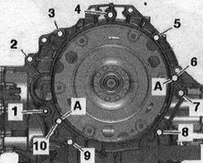
Vehicles with 3.2 l FSI engine and 3.0 l TDI engine: Check for the presence of centering bushings "A" of the engine and gearbox in the cylinder block; insert bushings if necessary.
Place the engine against the gearbox and tighten bolts "6" and "7" connecting the engine/gearbox.
All
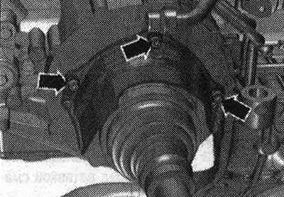
Screw on the tunnel-type cross beam. The tilter is not shown in the figure. Lower and set aside the lift with the gearbox mount J40173-. Tighten the engine-to-gearbox mounting bolts accessible from below. Remove the transport protection "T40170" and the mounting device "T40169". The next stage of work is necessary to ensure uniform contact with the driven disk without distortion. Press the clutch module "2" with the mounting lever "1" to the driven disk -3 "arrow".
Vehicles with 2.0 l TFSI engine and 2.0 l TDI engine: Tighten the clutch module bolts on the driven plate as follows: Screw in the first bolt "arrow" all the way (2 Nm).
Vehicles with 2.0 l TFSI engine: Turn the crankshaft by the central bolt of the damper using the counter support "T10355" by 240° in the direction of engine rotation. Ignore the "arrow". In this position of the crankshaft, tighten the accessible bolt to the specified torque. Then turn the crankshaft by 120° and tighten the remaining 2 bolts to the specified tightening torque.
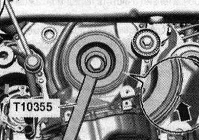
Vehicles with 2.0 l TDI engine: Turn the crankshaft by the central bolt of the damper by 240° in the direction of engine rotation. Ignore the "arrows". In this position of the crankshaft, tighten the accessible bolt to the specified torque. Then turn the crankshaft by 120° and tighten the remaining 2 bolts to the specified tightening torque.
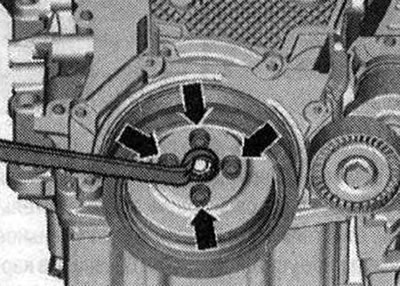
Vehicles with 3.2 l TFSI engine and 3.0 l TDI engine: Tighten the clutch module bolts on the driven disk as follows: Screw in the first bolt "arrow" all the way (2 Nm).
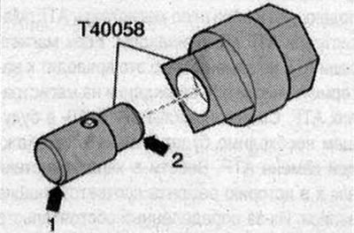
Insert the guide pin of the adapter "T40058" as follows: the large diameter "arrow 1" faces the engine, the small diameter "arrow 2" faces the adapter.
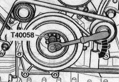
Rotate the vibration damper crankshaft using the adapter "T40058" by 180° in the direction of engine rotation "arrow". In this position of the crankshaft, tighten the accessible bolt with the specified torque. Rotate the crankshaft further by 60° accordingly and tighten the remaining 5 bolts with the specified tightening torque.
All
Installation is carried out in the reverse order, taking into account the following. Screw the universal joint to the steering gear. Install the selector cable. Install the ATF lines. Screw the left and right drive shafts to the shafts with the gearbox flange. Install the drive shaft heat shield. Using the vehicle data plate or the marking on the rear final drive, determine the type of rear final drive installed. Then select the appropriate repair manual for the rear final drive. Install the propeller shaft.
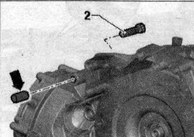
Cars with 2.0 l TFSI engine and 2.0 l TDI engine: Bolt "2" secures the starter to the gearbox and is additionally equipped with a spacer sleeve "arrow". The spacer sleeve must be installed between the starter and the gearbox.
All
Install the starter. Tighten the remaining bolts "3...5" connecting the engine/gearbox. Install the exhaust system and secure it without mechanical stress. Install the subframe cross braces. Install the PTO shaft covers and sound insulation. Fill the power steering fluid. Perform the necessary actions after connecting the battery. Check and adjust the selector cable.
Tightening torques (Nm)
Note: Tightening torques are only valid for lightly greased, oiled, phosphated or blued nuts and bolts. The use of additional lubricants such as engine or transmission oil is permitted, with the exception of lubricants containing graphite. Do not use degreased parts. Tightening torque tolerance ±15%.
| Bolts and nuts | |
| M6 | 9 |
| M7 | 15 |
| M8 | 20 |
| M10 | 40 |
| M12 | 65 |
Drive shaft heat shield tightening torque
Tighten the drive shaft heat shield arrow bolts to 23 Nm.
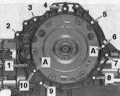
Dual-clutch transmission for 2.0L TFSI engine
| Pos. | Bolt | Nm |
| 1(1) | M 10x50 (2) | 65 |
| 2(3), 7 | M12X100 (4) | 30 + 90° |
| 3 (5), 6 | M 12x75 (4) | 30 + 90° |
| 4, 5(5) | M12X120 (4) | 30 + 90° |
| 8,9 | M10X75 (4) | 15 + 90° |
| 10 | M12X50 (4) | 30 + 90° |
| A | Centering bushings | |
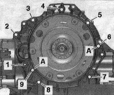
Dual-clutch transmission for 3.2L FSI engine
| Pos. | Bolt | Nm |
| 1(1) | M 10x50 (2) | 65 |
| 2 (3), 3...6 | M12x100 (4) | 30 + 90° |
| 7 | M12x125(4) | 30 + 90° |
| 8, 9, 10 | M10x60 (4) | 15 + 90° |
| A | Centering bushings | |
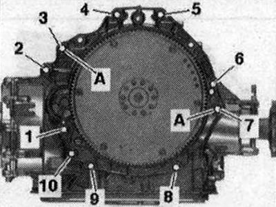
Dual-clutch transmission for 2.0L TDI engine
| Pos. | Bolt | Nm |
| 1(1) | M10x60 (2) | 65 |
| 2(3) | M12X100 (4) | 30 + 90° |
| 3 (5), 6 | M 12x75 (4) | 30 + 90° |
| 4,5 | M12x120 (4) | 30 + 90° |
| 7,8 | M10x60 (4) | 15 + 90° |
| 9 | M10x60 (4) | 30 + 90° |
| A | Centering bushings | |
- (1) Additionally secure the starter.
- (2) The bolt strength is 10.9, the steel bolt can be used unlimited times.
- (3) Additionally secures the starter; equipped with an additional spacer sleeve between the starter and gearbox.
- (4) Bolts can be used twice.
- (5) Additionally secures the wiring bracket.
Dual-clutch transmission for 3.0L TDI engine
| Pos. | Bolt | Nm |
| KP | M10x50 (2) | 65 |
| 2(3), 3...6 | M12x100 (4) | 30 + 90° |
| 7 | M12X125 (4) | 30 + 90° |
| 8 | M10x60 (4) | 15 + 90° |
| 9,10 | M10x95 (4) | 15 + 90° |
| A | Centering bushings | |
- (3) Additionally secure the starter.
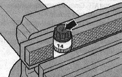
Aluminum bolts can be used twice. Therefore, after the first use, mark such bolts with two notches "X" "arrow" with a cutter. In order not to damage the bolts when notching, do not fasten them in a vice. Insert the bolt as shown in the picture into a 14 socket head with a 1/2 inch drive, which can then be fastened in a vice. Do not reuse bolts marked with "X".
The original text is available on the website AUDIMANUAL