
Remove sound insulation "1" and "2". Remove the strut brace. Remove the catalyst on the right.
Remove the left additional muffler.
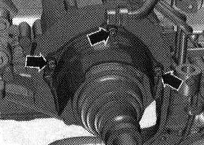
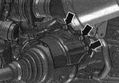
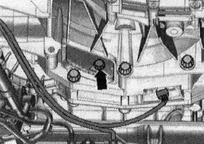
Unscrew the "arrow" bolts of the ATF lines.
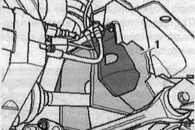
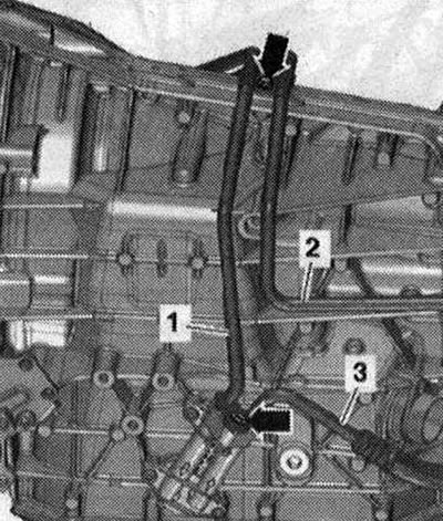
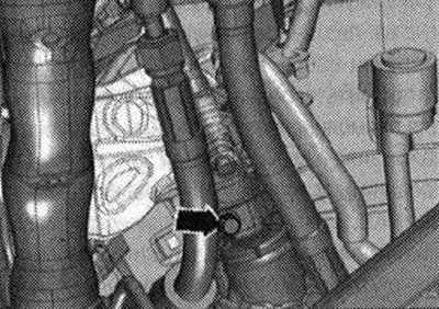
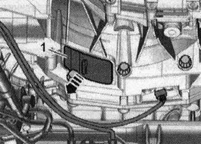
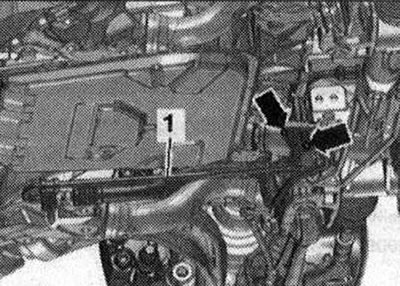
Cars with an ATF line, filter: To collect the leaking ATF oil, place a rag under the disconnection point. Unscrew the bolts "arrows" and disconnect the ATF line "1" from the gearbox. Ignore "Pos. 2, 3".
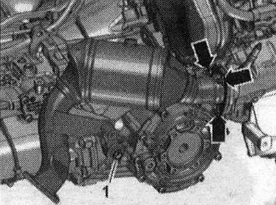
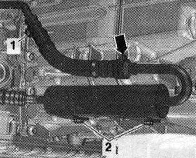
Unscrew bolt "1". Disconnect the ATF line from the ATF line filter, for which remove the clamp "arrow". Ignore "Pos. 2".
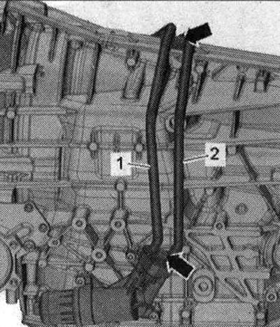
Tie up ATF lines "1" and "2" at the top. Do not take "Pos. 3" into account. Close open lines and pipes with clean plugs from the plug set for the "VAS 6122" engine.
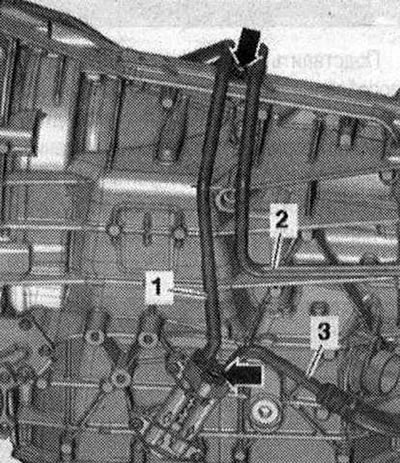
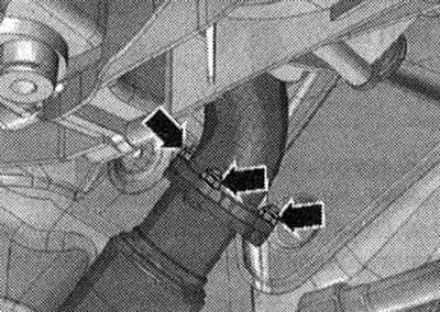
Cars with replaceable ATF filter: Unscrew the bolts "arrow", disconnect the ATF lines "1" and "2" from the gearbox and secure them from above. Close the open lines and pipes with clean plugs from the plug set for the "VAS 6122" engine.
All
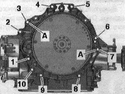
Unscrew the bolts "2...5" that connect the gearbox and engine and are accessible from above. - Take into account pos.
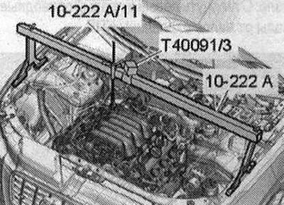
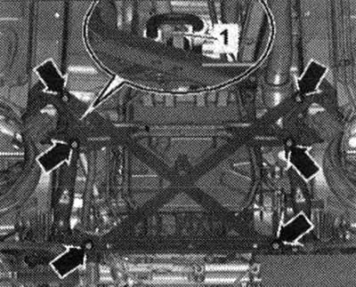
Install the "10 - 222 A" crossmember with the "T40091/3" connector on the shock absorber strut cups on the left and right, as shown in the figure. Fasten the "10 - 222 A/11" lead screw to the right engine suspension eye.
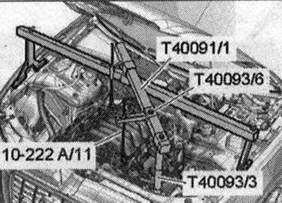
Install other parts of the crossmember "10222 A" as shown in the figure. To do this, install the support "T40093/3" on the fold of the side member sheet. Fasten the lead screw "10 -222 A/11" to the left front eye of the engine suspension. Preliminarily slightly tighten the engine with the lead screws.
Unscrew the "arrow" bolts and remove the heat-insulating shield of the right drive shaft.
Unscrew the "arrow" bolts and remove the heat-insulating shield of the left drive shaft. Unscrew the left and right drive shafts from the shafts with the gearbox flange.
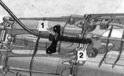
Unfasten the ball joint "2" of the selector cable with the release lever "80 - 200" from the gearbox lever. Remove the locking bracket "1" and release the selector cable.
Caution! Risk of failure of the gearbox control unit (Mechatronik) due to static discharge. Before working with electrical connectors, a specialist must "discharge the electrostatic charge". For example, touch the car ground, heater or lift with your hand. Do not touch the contacts in the gearbox plug with your hands.
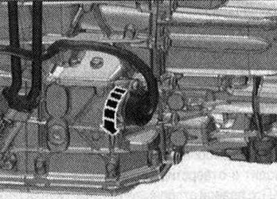
Disconnect the GEARBOX plug connector by turning the rotary clamp counterclockwise "arrow".
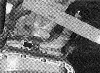
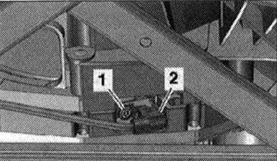
Disconnect connector "2" of engine speed sensor "G28" and release the gearbox electrical wire. Ignore "Pos. 1".
Caution! Risk of damage to the airbag coil spring. Only disconnect the universal joint from the steering gear when the front wheels are in the straight-ahead position. Do not change the position of the steering wheel or steering gear any further; if necessary, secure the steering wheel with adhesive tape.
Unscrew the bolt "arrow" of the universal joint. Press the universal joint of the steering gear and move it completely upward.
Remove the subframe cross braces. Risk of damage to chassis components. If the unit support, steering gear or subframe cross brace is not properly mounted, the vehicle cannot be placed on its wheels.
If present, unscrew the "arrow" bolts and remove the heat shield "1" of the propeller shaft.
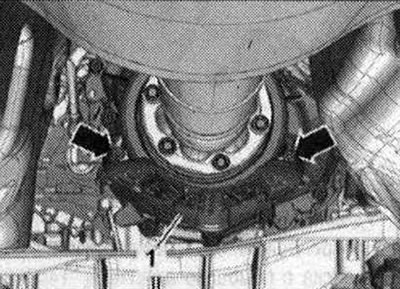
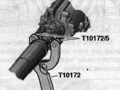
Car with a bolted cardan shaft: Unscrew the bolts connecting the cardan shaft and gearbox, while holding it from turning using the counter support "T10172" with "T10172/5". Move the cardan shaft towards the rear main gear; constant velocity joints are movable in the axial direction. Tie the cardan shaft to the side.
Vehicles with plug-in propeller shafts: Use the vehicle data plate or the rear final drive marking to determine the type of rear final drive installed. Then select the appropriate repair manual for the rear final drive. Remove (inserted) cardan shaft.
All
Remove the cover "1" under the gearbox "arrow".
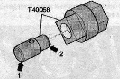
Insert the guide pin of the adapter "T40058" as follows: the large diameter "arrow 1" faces the engine; small diameter "arrow 2" is directed towards the adapter.
Hold or turn the crankshaft to loosen the driven disk mounting bolts using the adapter "T40058". During the final turn, turn the crankshaft only in the direction of engine rotation "arrow".
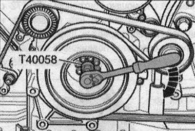
Unscrew the 6 bolts "arrow" of the driven disk, to do this, turn the crankshaft accordingly through 60° in the direction of engine rotation.
Place a device for filling and pumping out oil under the place of separation. Unscrew the bolts "arrows", disconnect the hydraulic line "1" from the steering gear and put it aside. Close the open lines and pipes with clean plugs from the plug set for the engine "VAS 6122".
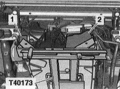
Unscrew bolt "1" of the starter. Remove the starter from the gearbox and leave it in the installation position. Unscrew the remaining bolts "6...10" connecting the gearbox to the engine. Do not take "Pos. A" into account. Risk of depressurization of the ATF pan. Do not touch the ATF pan with the gearbox support "T40173". Install the powertrain lift with the prepared gearbox mount "T40173" under the gearbox. From the front, the gearbox mount must be installed as follows: on the left side, the fastening block "2" goes into the hole for the flywheel on the gearbox housing; on the right side of the gearbox, the elastic gearbox mounting gasket "1" touches the central differential housing.
Secure the gearbox with tension belt "1". Unscrew the bolts "arrow" of the tunnel crossmember. The tilter is not shown in the figure. Press the gearbox away from the engine and carefully lower it using the tilter.