
Repair Chevrolet Repair Toyota Repair Honda Repair AvtoVAZ Repair Mercedes-Benz Repair BMW Repair Opel
Home  |  Contacts  |  Sitemap  |    
English Русский
Български
Беларускі
Український
Српски
Hrvatski
Română
Polski
Slovenský
Magyar
AudiManual.ru


  • AUDI 80
  • AUDI 100
  • AUDI A3
  • AUDI A4
  • AUDI A6
  • AUDI A8
  • AUDI Q
  • OTHER
  • ARTICLES
Q7 Typ 4L (2005-2015, diesel) Q5 Type 8R (2008-2017)

Removal the gear shift module functional unit (Audi Q5-8R)

  • Home
  • Audi Q
  • Q5 Type 8R (2008-2017)
  • Transmission
  • Automatic gearbox 0B5
  • Removal the gear shift module functional unit
            0
Table of contents: All ↓ Installation ↓
Remove the front ashtray. Disconnect electrical connectors "2" and "4". The damping mat is not shown in the figure. When removing the gearshift mechanism under the car, the help of a second mechanic is required. Remove the damping mat above the gearshift mechanism. Unscrew bolts "1,3,5,6".
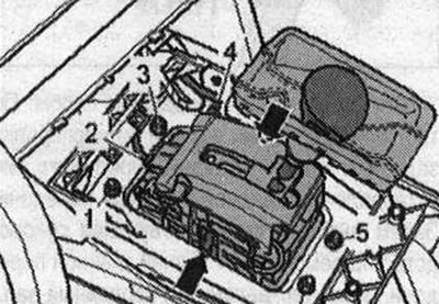
Remove the front ashtray. Disconnect electrical connectors «2» and «4». The damping mat is not…


Remove the subframe cross braces. Risk of damage to running gear parts; if the unit support, steering gear or subframe crosspiece is not properly mounted, the vehicle cannot be placed on its wheels.
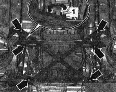
Remove the subframe cross braces. Risk of damage to running gear parts; if the unit support,…


If present, unscrew the "arrow" bolts and remove the heat shield "1" of the propeller shaft.
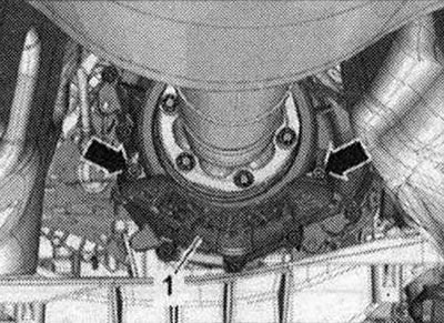
If present, unscrew the «arrow» bolts and remove the heat shield «1» of the propeller shaft.


Car with a bolted cardan shaft: Unscrew the bolts connecting the cardan shaft and gearbox, while holding it from turning using the counter support "T10172" with "T10172/5". Move the cardan shaft towards the rear main gear; constant velocity joints are movable in the axial direction. Place the cardan shaft on the front crossmember.
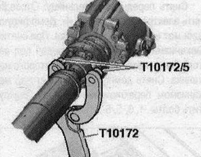


Car with a bolted cardan shaft: Unscrew the bolts connecting the cardan shaft and gearbox, while…


Vehicles with a plug-in propeller shaft: Use the vehicle data plate or the rear final drive marking to determine the type of rear final drive installed. Then select the appropriate repair manual for the rear final drive. Remove (inserted) cardan shaft.
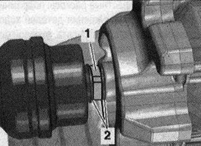
Vehicles with a plug-in propeller shaft: Use the vehicle data plate or the rear final drive marking…


Cars with a single-flow exhaust system: Loosen the screw connections "arrows", move the clamping sleeve back and tie the front exhaust pipe to the body.
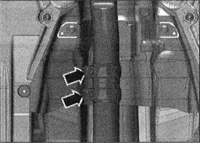
Cars with a single-flow exhaust system: Loosen the screw connections «arrows», move the clamping…


Cars with a dual-flow exhaust system: Loosen the mounting sleeve "1" and "2", move it back and secure the additional muffler to the body.
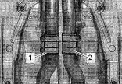


Cars with a dual-flow exhaust system: Loosen the mounting sleeve «1» and «2», move it back and…


All


Install the gearbox support "T10337" on the engine and gearbox lift and place it underneath the gearbox. Raise the gearbox slightly
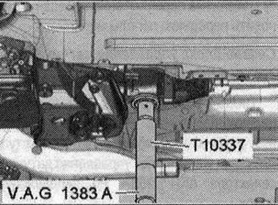
Install the gearbox support «T10337» on the engine and gearbox lift and place it underneath the…


Unscrew the bolts of the tunnel cross member "arrow".
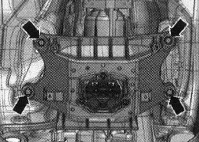
Unscrew the bolts of the tunnel cross member «arrow».


Lower the CP with a tilter by the value "a". The value "a" = maximum 100 mm.
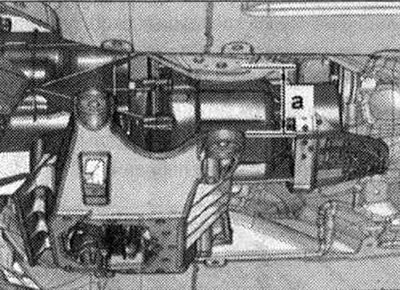
Lower the CP with a tilter by the value «a». The value «a» = maximum 100 mm.


Unfasten the ball joint "2" of the automatic transmission selector cable with the release lever "80-200" from the gearbox lever. Remove the locking bracket "1" and disconnect the automatic transmission selector cable from the gearbox. The selector cable must not be bent or broken.
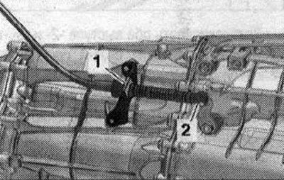


Unfasten the ball joint «2» of the automatic transmission selector cable with the release lever…


If present, unscrew the "arrow" nuts. Lower the bottom trim from the inside so that the heat shield "1" of the central tunnel can be removed. Remove the gearbox shift mechanism.
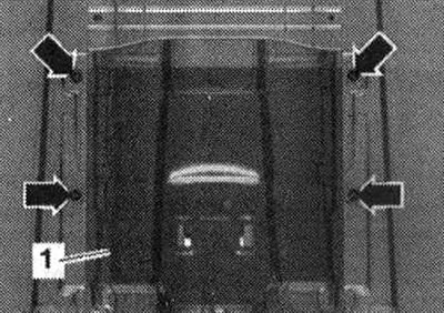
If present, unscrew the «arrow» nuts. Lower the bottom trim from the inside so that the heat shield…


Installation


Installation is carried out in the reverse order. Before installation, lightly lubricate the ball joint of the selector cable with polyurea grease "G 052 142 A2". The selector cable must not be bent or broken. Adjust the gearbox selector cable. Install the heat shield. Install the tunnel cross member. Check the gearshift drive. Align the exhaust system without mechanical stress. Using the vehicle data plate or the marking on the rear final drive, determine the type of rear final drive installed. Then select the appropriate repair manual for the rear final drive. Install the propeller shaft. Install the subframe cross braces. Install the front ashtray. After removing and installing the shift drive functional unit, perform the corresponding "Guided Function" using the diagnostic tester.
The article was checked by auto expert Timur Bazhenov
This article is available at russian, bulgarian, belarusian, ukrainian, serbian, croatian, romanian, polish, slovak, hungarian

Share information:
Previous articles
Audi Q Q5 Type 8R: Automatic gearbox 0B5
Next articles

Removal the selector position switch P «F305»
Removal the gear selector sensor control unit «J587»
Removal the selector lock solenoid «N110»
Emergency release of the gearshift mechanism
Automatic transmission selector handle, automatic transmission…
Selector lever cable
Removal the gearbox — vehicles with a 2.0 l TFSI engine
Removal the gearbox — vehicles with a 3.2 l FSI engine


Similar articles on other Audi car models:
Gear shift lever — removal, overhaul and installation Audi 80 B3 (1986-1991, petrol)
Gear shift lever Audi 100 C3 (1982-1990, diesel)
Gear shift drive Audi A3 Type 8L (1996-2003)
Mounting position of the gear shift mechanism Audi A4 B8 (2007-2015)
Adjusting the gear shift mechanism Audi A6 C5 (1997-2004)
Main reverse gear Audi A8 D2 (1994-2002)
Gear shift unit — design description Audi A2 (1999-2005)
Link to this page in different formats


Visitor comments

No comments yet


How much will 13 + 16 =


Q7 4L(2005-2015, diesel) 
  • General information
  • Operating instructions
  • Maintenance
  • Power unit
  • Diesels 3.0 l (BUG, BUN, CAS)
  • Diesels 3.0 l (CATA, CCMA)
  • Diesels 3.0 l (CJGA/CJGC)
  • Diesels 4.2 l (BTR, CCFA/CCFC)
  • Cooling system
  • Fuel and exhaust system
  • Engine management system
  • Starting and charging
  • Transmission
  • Automatic gearbox
  • Drive shafts
  • Chassis
  • Brake system
  • Front suspension
  • Rear suspension
  • Steering system
  • Body
  • Air conditioner
  • Exterior
  • Interior
  • Electrical equipment
  • Equipment and devices
  • Electrical circuits
 
Q5 8R(2008-2017) 
  • General information
  • User manual
  • Power unit
  • Petrol engine 2.0 l
  • Petrol engine 3.2 l
  • Fuel system (petrol)
  • Diesel 2.0 liter (CA)
  • Diesel 2.0 liter (CG/CJ/CM)
  • Diesel engine 3.0 l
  • Fuel system (diesel)
  • Transmission
  • Manual gearbox 0B1
  • Manual gearbox 0B2
  • Automatic gearbox 0B5
  • Automatic gearbox 0B6
  • Chassis
  • Front suspension
  • Rear suspension
  • Brake system
  • Steering
  • Body
  • Exterior
  • Interior
  • Doors, locks and windows
  • Safety system
  • Ventilation and heating
  • Electrical equipment
  • Power devices
  • Equipment and devices
  • Lighting and alarm
  • Audio system
  • Electrical circuits
 
AudiManual.ru © 2017-2026 · Mobile version · Feedback · Sitemap: EN BG BY UA RS HR RO PL SK HU · Site search · News and articles
80 B2 · 80 B3 petrol · 80 B3 · 80 B4 · 100 C3 diesel · 100 C3 petrol · 100 C3 · 100 C4 petrol · 100 C4 · A3 Type 8L · A4 B5 petrol · A4 B5 · A4 B6 petrol · A4 B6 · A4 B7 · A4 B8 · A6 C4 · A6 C5 · A6 C5 Allroad · A8 D2 · Q5 Type 8R · Q7 Typ 4L · Audi A2 ·
This site uses cookies 🍪. Click the button to accept this fact.