
Set the front wheels to the straight-ahead position. Turn off the ignition and remove the ignition key. Disconnect ground wire -arrow- from ACV terminal. Pump out the power steering hydraulic oil using a device for pumping out oil from the expansion tank. tank.
Remove engine cover -arrows-. Remove the strut spacer.
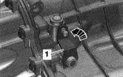
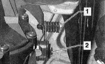
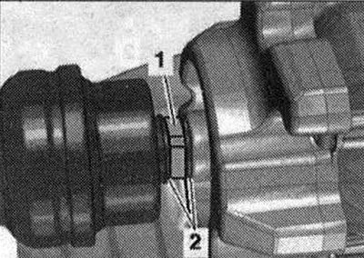
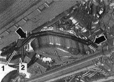
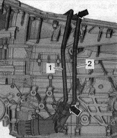
Unfasten the ball bearing -2- of the selector cable using a release lever -80 - 200- from the gearbox lever. Remove the locking bracket -1- and release the selector cable. The selector cable must not be bent or broken.
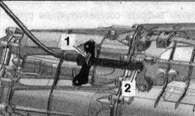
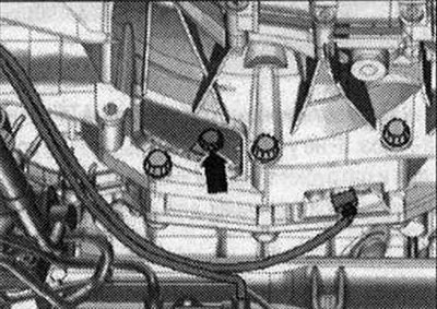
Unscrew the bolts -2...5- accessible from above connecting the gearbox and engine. -Pos. A-ignore.
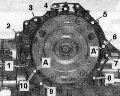
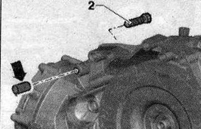
Remove the starter from the gearbox and leave it in its installation position. Bolt -2- secures the starter to the gearbox and is additionally equipped with a spacer sleeve -arrow-.
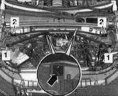
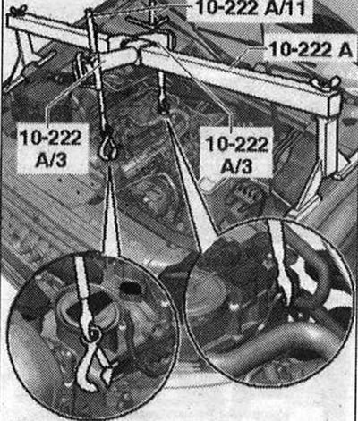
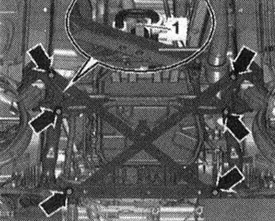
Install the cross member -10 - 222 A- with adapters -10 - 222 A/3- onto the cups of the left and right shock absorber struts, as shown in the figure. Secure the lead screws -10 -222 A/11- to the engine mounting lugs. Lightly tighten the motor with the lead screws first.
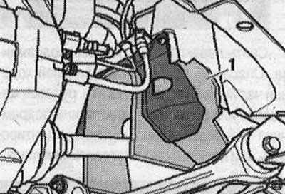
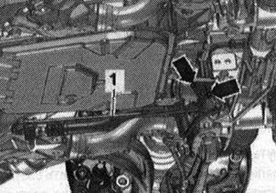
Remove the front wheels. Remove the cover -1 - of the drive shaft in the wheel arch on the left and right.
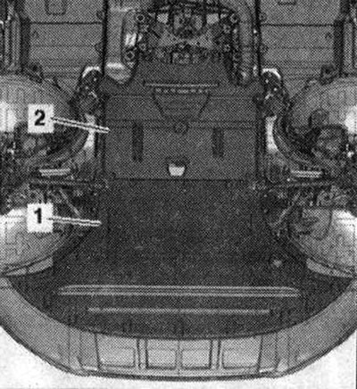
Remove sound insulation -1- and -2-.
Unscrew bolt-1-.
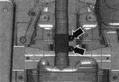
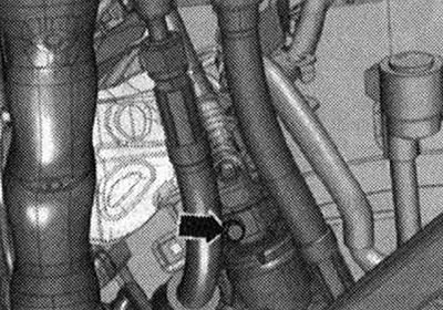
Unscrew the connections -arrows- and move the clamping sleeve to the rear.
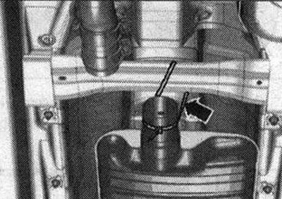
Lower the front muffler slightly and attach it to the cross member -arrow-.
Remove the cross braces from the subframe. Risk of damage to chassis parts. If the unit support, steering gear or subframe spacer is not mounted properly, the vehicle will not be able to be placed on wheels.
If present, remove bolts -arrows- and remove heat shield -1- for propeller shaft.
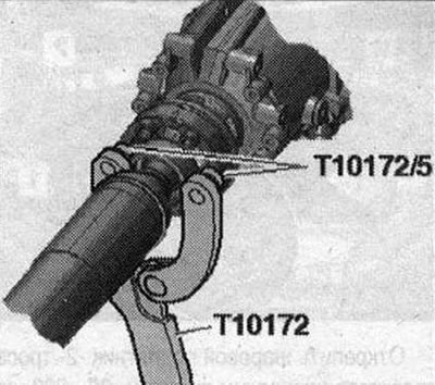
Vehicles with a bolted propeller shaft: Unscrew the bolts connecting the propeller shaft and gearbox, while holding them against turning using the counterhold -T10172- with -T10172/5-. Move the cardan shaft to the rear main gear; constant velocity joints are movable in the axial direction. Tie the driveshaft to the side.
Vehicles with a plug-in propeller shaft: Use the vehicle data plate or the rear final drive marking to determine the type of rear final drive installed. Then select the appropriate repair manual for the rear final drive. Remove the driveshaft (plug-in).
All
Carefully! Risk of failure of the gearbox control unit (Mechatronik) due to static discharge. Before working with email. connectors must be installed by a specialist "discharge electrostatic charge". For example, touching the vehicle's ground, heater or lift with your hand. Do not touch the contacts in the gearbox plug with your hands.
Disconnect the gearbox connector by turning the rotary clip counterclockwise -arrow-. Release the wiring harness.
Unscrew bolts -arrows- for ATF lines. -Pos. 1,2 - do not take into account.
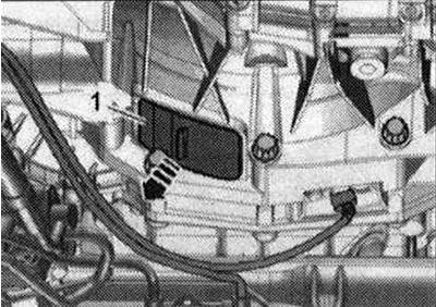
Vehicles with a master ATF filter: To collect leaking ATF oil, place a rag under the disconnect points. Unscrew bolt -1 -. Disconnect the ATF line from the ATF line filter by removing the clamp -arrow-. -Pos. 2- do not take into account.
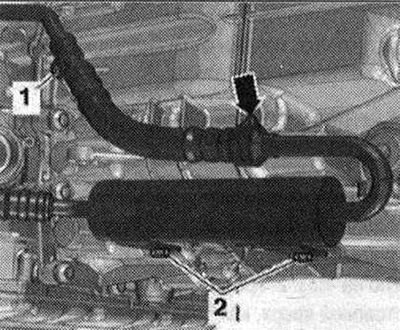
Unscrew bolt -arrow-, disconnect ATF line -1 - from gearbox and place to one side. -Pos. 2- do not take into account. Seal open lines and pipes with clean plugs from the engine plug set -VAS6122-.
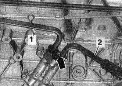
Vehicles with replacement ATF filter: Unscrew bolts -arrow-, disconnect ATF lines -1- and -2- from gearbox and secure from above. Seal open lines and pipes with clean plugs from the engine plug set -VAS 6122-.
All
Carefully! Risk of damage to the coiled Airbag spring. Disconnect the universal joint from the steering gear only with the front wheels mounted straight. Do not change the position of the steering wheel and steering gear any more; to do this, if necessary, secure the steering wheel with electrical tape.
Remove bolt -arrow- from universal joint. Press the steering gear universal joint out and push it all the way up.
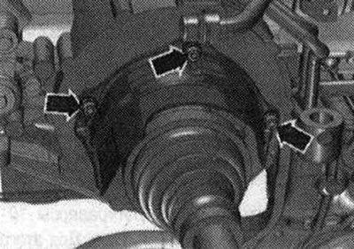
Unscrew the bolts -arrows- and remove the heat insulation shield for the right drive shaft. Unscrew the left and right drive shafts from the shafts with the gearbox flange.
Remove trim -1- under gearbox -arrow-.
Hold or rotate the crankshaft to loosen the drive disc bolts using the support -T10355-. During the final turn, rotate the crankshaft only in the direction of engine rotation. -Arrow- do not take into account.
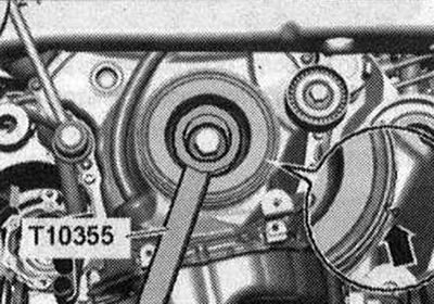
Unscrew the 3 bolts -arrow- of the driven disc; to do this, rotate the crankshaft through 120°in the direction of engine rotation.
Place a device for filling and pumping out oil under the separation area. Unscrew bolts -arrows-, disconnect hydraulic line -1- from steering gear and place to one side. Seal open lines and pipes with clean plugs from the engine plug set -VAS 6122-.
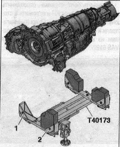
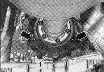
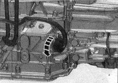
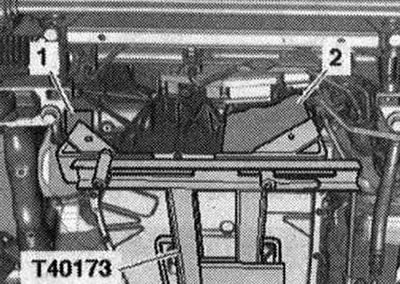
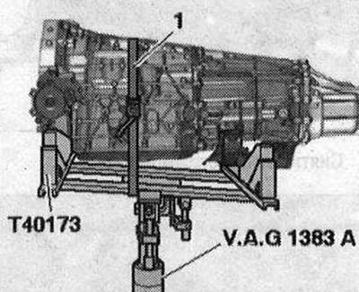
Remove starter bolt -1-. Remove the starter from the gearbox and leave it in its installation position. Remove the remaining bolts -6...10- connecting the gearbox to the engine. -Pos. A - ignore. Danger of depressurization of the ATF pan. Do not touch the ATF pan with the gearbox support -T40173-. Place the powertrain lift with the prepared gearbox mount -T40173- under the gearbox. At the front, the gearbox mount must be installed as follows: on the left side, the mounting block -2- fits into the hole for the flywheel on the gearbox housing; On the right side of the gearbox, the elastic mounting gasket for the gearbox -1- touches the central differential housing.
Secure the gearbox using the tensioning belt -1-.
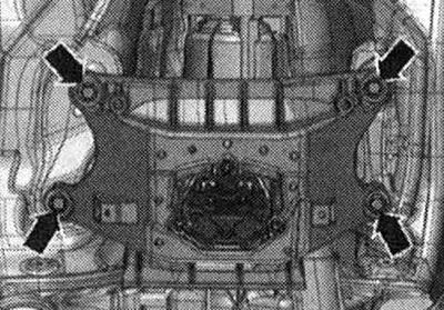
Unscrew the bolts -arrows- for the tunnel cross member. The picture does not show the tilter. Press the gearbox away from the engine and carefully lower it using the tilt lever.
Visitor comments