Repair Chevrolet Repair Toyota Repair Honda Repair AvtoVAZ Repair Mercedes-Benz Repair BMW Repair Opel
Home  |  Contacts  |  Sitemap  |    
English Русский
Български
Беларускі
Український
Српски
Hrvatski
Română
Polski
Slovenský
Magyar
AudiManual.ru


  • AUDI 80
  • AUDI 100
  • AUDI A3
  • AUDI A4
  • AUDI A6
  • AUDI A8
  • AUDI Q
  • OTHER
  • ARTICLES
Q7 Typ 4L (2005-2015, diesel) Q5 Type 8R (2008-2017)

Electromechanical steering gear — disassembly and assembly (Audi Q5-8R)

  • Home
  • Audi Q
  • Q5 Type 8R (2008-2017)
  • Chassis
  • Steering
  • Electromechanical steering gear — disassembly and assembly
            0
Electromechanical steering mechanism 1. Clamp. Replace each time it is removed. Use the clamping…

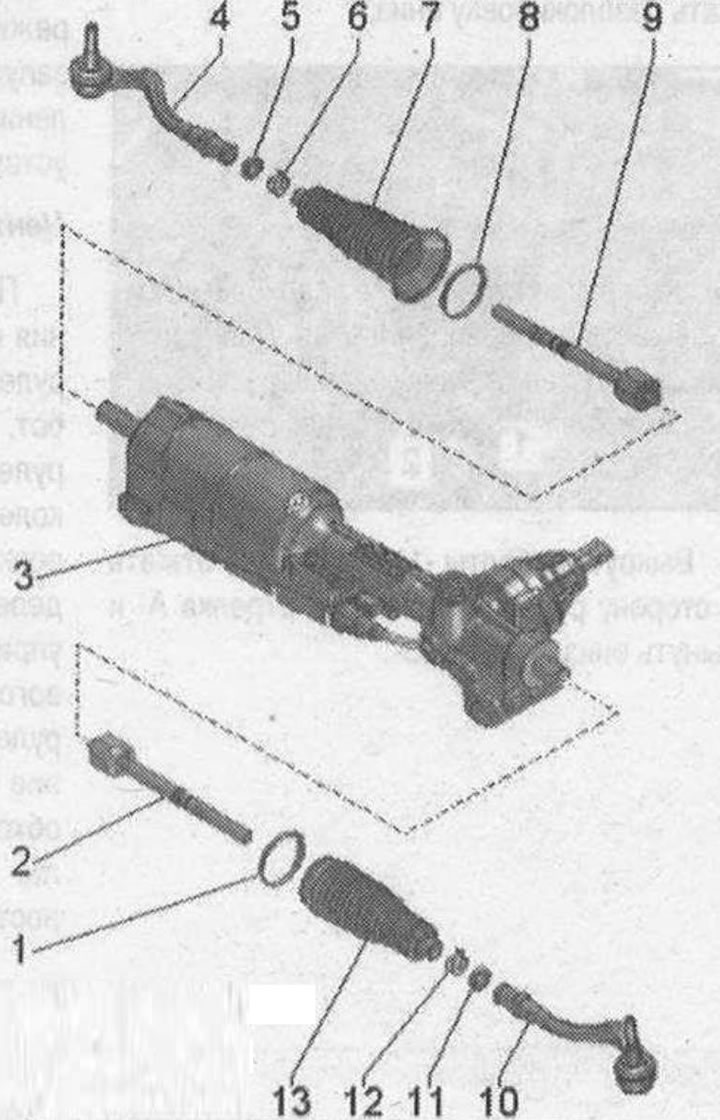
Electromechanical steering mechanism 1. Clamp. Replace each time it is removed. Use the clamping pliers "VAG 1682 A" to tighten the clamping clamp. Opening and bending the new clamping clamp is prohibited; 2. Transverse tie rod. 100 Nm. Lubricate the joint with steering gear grease; 3. Electromechanical steering gear. Lubricate the toothed rack with consistent grease for steering gears. It should be noted that different types of grease are used on the right and left; 4. Tie rod end. Check for proper fit and absence of damage to the boot; 5. Nut. 80 Nm. When loosening or tightening, hold the tie rod end from turning; 6. Spring clamp. Replace each time it is removed. Installing the clamp clamp; 7. Corrugated boot. Check for damage. Replace each time it is removed. Before installing the corrugated boot socket, apply consistent grease for steering gears evenly around the perimeter inside. Before installing the corrugated boot socket on the steering gear housing, check for leaks. If the seal kit on the steering gear housing is damaged, the steering gear must be replaced. When setting the wheel alignment, twisting is not allowed. Ensure correct installation; 8. Clamp. Replace each time when removed. Use clamping pliers "VAG 1682 A" to tighten the clamp clamp; 9. Transverse tie rod. 100 Nm. Lubricate the joint with steering gear grease; 10. Tie rod end. Check for proper fit and absence of damage to the boot; 11. Lock nut. 80 Nm. When loosening or tightening, hold the tie rod end from turning; 12. Spring clamp. Replace each time it is removed. Installing the clamp clamp; 13. Bellows. Check for damage. Replace each time it is removed. Before installing the bellows seats, apply consistent grease for steering gears evenly around the perimeter inside. Before installing the bellows seat on the steering gear housing, check for leaks. If the seal kit on the steering gear housing is damaged, the steering gear must be replaced. When adjusting the wheel alignment, twisting is not allowed. Ensure correct installation


Note: Replace the self-locking nuts and screws. Welding and straightening work on parts of the steering gear is not allowed. For lubrication of the toothed rack (from the gear side) or grooves for balls (from the engine side) use only consistent grease for steering gears. It should be noted that different types of grease are used on the right and left. The tension of clamping clamps "1 and 8" is produced by different tightening torques.


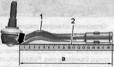
Control size of the steering rod end


Apply steel ruler "2" to the end of the tie rod and push it to the edge "arrow" at the end of the tie rod end "1" until it stops. If the control dimension "a" = less than 188 mm, the tie rod with the end should be replaced.

Apply steel ruler «2» to the end of the tie rod and push it to the edge «arrow» at the end of the…


Tighten the clamp: Install the pliers -VAG 1682 A-1- as shown in the figure.

In doing so, make sure that the jaws of the pliers fit tightly against the corners of the clamp's "arrow". Tighten the clamp by turning the lead screw with a torque wrench "2" (do not tilt the pliers).

In doing so, make sure that the jaws of the pliers fit tightly against the corners of the clamp's…


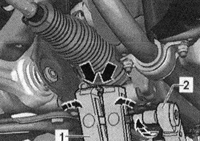
Use a torque wrench with an adjustment range of 5...50 Nm (e.g "V.A.G 1331"). Monitor the ease of movement of the thread of the lead screws of the pliers "VAG 1682 A" "1". If necessary, apply MoS2 grease. If rotation is difficult, for example due to contamination of the thread, the required clamping force is not achieved at the specified tightening torque.

[Information obtained from this resource: AUDImanual]
The article was checked by auto expert Timur Bazhenov
This article is available at russian, bulgarian, belarusian, ukrainian, serbian, croatian, romanian, polish, slovak, hungarian

Share information:
Previous articles
Audi Q Q5 Type 8R: Steering
Next articles

Electromechanical steering mechanism
Removal the Active Steering System Safety Lock
Removal the ELV-J764 control unit-
Removal the steering column
Removal the tie rod end
Removal the tie rod
Hydraulic steering gear
Removal the hydraulic power steering


Similar articles on other Audi car models:
Carburetor — disassembly, cleaning and assembly Audi 80 B3 (1986-1991, petrol)
Gear shift rod (013 and 093) — disassembly and assembly Audi 100 C3 (1982-1990, diesel)
Adjustable steering column Audi A3 Type 8L (1996-2003)
Removal and installation, disassembly and assembly of gear… Audi A4 B7 (2004-2008)
Disassembly and assembly of the shock absorber strut Audi A6 C5 (1997-2004)
Disassembly and assembly of the shock absorber strut Audi A8 D2 (1994-2002)
Assembly diagram, repair of gear shift lever and gearbox housing Audi A2 (1999-2005)
Link to this page in different formats


Visitor comments

No comments yet


How much will 17 + 24 =


Q7 4L(2005-2015, diesel) 
  • General information
  • Operating instructions
  • Maintenance
  • Power unit
  • Diesels 3.0 l (BUG, BUN, CAS)
  • Diesels 3.0 l (CATA, CCMA)
  • Diesels 3.0 l (CJGA/CJGC)
  • Diesels 4.2 l (BTR, CCFA/CCFC)
  • Cooling system
  • Fuel and exhaust system
  • Engine management system
  • Starting and charging
  • Transmission
  • Automatic gearbox
  • Drive shafts
  • Chassis
  • Brake system
  • Front suspension
  • Rear suspension
  • Steering system
  • Body
  • Air conditioner
  • Exterior
  • Interior
  • Electrical equipment
  • Equipment and devices
  • Electrical circuits
 
Q5 8R(2008-2017) 
  • General information
  • User manual
  • Power unit
  • Petrol engine 2.0 l
  • Petrol engine 3.2 l
  • Fuel system (petrol)
  • Diesel 2.0 liter (CA)
  • Diesel 2.0 liter (CG/CJ/CM)
  • Diesel engine 3.0 l
  • Fuel system (diesel)
  • Transmission
  • Manual gearbox 0B1
  • Manual gearbox 0B2
  • Automatic gearbox 0B5
  • Automatic gearbox 0B6
  • Chassis
  • Front suspension
  • Rear suspension
  • Brake system
  • Steering
  • Body
  • Exterior
  • Interior
  • Doors, locks and windows
  • Safety system
  • Ventilation and heating
  • Electrical equipment
  • Power devices
  • Equipment and devices
  • Lighting and alarm
  • Audio system
  • Electrical circuits
 
AudiManual.ru © 2017-2026 · Mobile version · Feedback · Sitemap: EN BG BY UA RS HR RO PL SK HU · Site search · News and articles
80 B2 · 80 B3 petrol · 80 B3 · 80 B4 · 100 C3 diesel · 100 C3 petrol · 100 C3 · 100 C4 petrol · 100 C4 · A3 Type 8L · A4 B5 petrol · A4 B5 · A4 B6 petrol · A4 B6 · A4 B7 · A4 B8 · A6 C4 · A6 C5 · A6 C5 Allroad · A8 D2 · Q5 Type 8R · Q7 Typ 4L · Audi A2 ·
This site uses cookies 🍪. Click the button to accept this fact.