
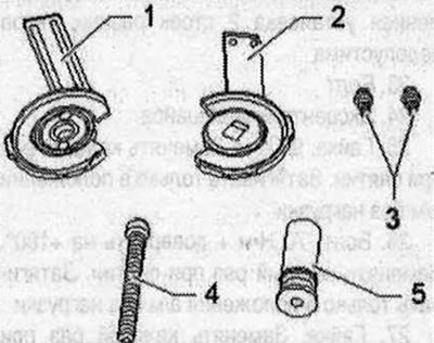
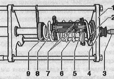
- 1. Thrust plate with swivel support -VAS 6274/1 anti-rotation protection with longitudinal holes -VAS 6274/11 -5- and spacer -VAS 6274/11 -4-
- 2. Thrust plate with lock washer -VAS 6274/11-2-, anti-rotation guard with guide bolts -VAS 6274/11 -6- and spacer -VAS 6274/11 -4-
- 3. The rotation stopper bolts are included in the additional kit. set Audi Q5 -VAS 6274/11 -
- 4. Lead screw -VAS 6274/10-4-
- 5. Bushing
- 6. Piston -VAS 6274/4- not shown
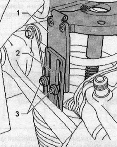
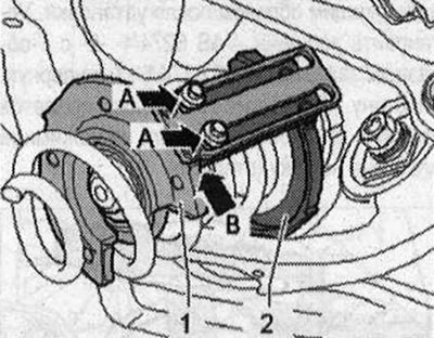
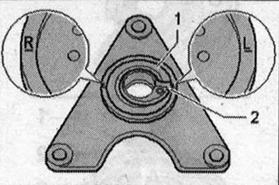
Before starting work, align the anti-rotation guard -1- using spacers -2- on the stop plates -3-, as shown in the figure, in area -A- according to the markings -arrow- and secure using the bolts included in the kit.
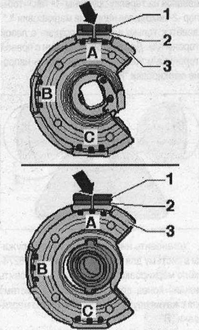
- 1. Top illustration: anti-rotation guard with guide bolts -VAS 6274/11-6-, Bottom illustration: anti-rotation protection with longitudinal holes -VAS 6274/11-5-
- 2. Spacer-VAS 6274/11-4-
- 3. Top illustration: anti-rotation protection with lock washer -VAS 6274/11-2-. Bottom illustration: Anti-rotation device with swivel support -VAS 6274/11-1-
Removal
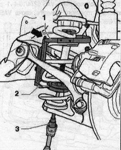
Place the vehicle on a lift. Remove the wheels. If necessary, move the safety lever against the -direction of the arrow-.
For clarity, in this and previous figures the work process is shown with the stone protection removed. Insert the thrust plate with lock washer -VAS 6274/11-2-, the anti-rotation guard with guide bolts -VAS 6274/11 -6- and the spacer -VAS 6274/11 -4- from the outside into the coil spring as high as possible and position it between the transverse suspension arm and tie rod. When installing a thrust plate with lock washer -VAS 6274/11-2-, anti-rotation protection with guide bolts. VAS 6274/11-6- and spacers -VAS 6274/11-4- there is not enough space, the tools must be separated, installed separately and connected properly after installation. Place piston -VAS 6274/4- -2- with T-piece -VAS 6274/5-3- into thrust plate. To do this, you may have to move the safety lever on the pressure plate outward (open).
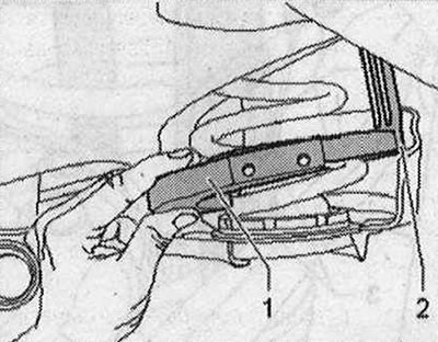
Press the safety lever in -direction of the arrow- to secure the position of the piston. Turn the thrust plate with lock washer -VAS 6274/11 -2-, the anti-rotation guard with guide bolts -VAS 6274/11-6- and the spacer -VAS 6274/11-4- completely upwards. Insert thrust plate with swivel support -VAS 6274/11 -1 -, anti-rotation guard with longitudinal holes -VAS 6274/11-5- and spacer -VAS 6274/11- -4- from the inside between the lower wishbones and the tie rod. into the coil spring as low as possible; if necessary, move the crankcase guard slightly to the side. If to install a thrust plate with a rotating support -VAS 6274/1 anti-rotation protection with longitudinal holes. VAS 6274/11-5- and spacers -VAS 6274/11-4- there is not enough space, the tools must be separated, installed separately and connected properly after installation. Screw the pressure plate with the hinge support to its lowest position. The rotation stop -2- must be located between the tie rod and the suspension wishbone.
Before each spring is removed or installed, the lead screw must be lubricated with a thin layer of the supplied lubricant. Lubricate the lead screw only with the lubricant supplied. Using other lubricants may damage the lead screw. Apply a thin layer of grease to the front part of the spindle -VAS 6274/10-4-.
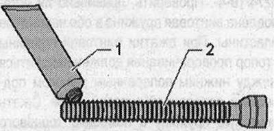
- 1. Tube of lubricant from the spring compression system kit -VAS 6274- or from the accessory. set -VAS 6274/10-
- 2. Lead screw -VAS 6274/10-4-. Lightly tighten the spindle -VAS 6274/10-4--1- using the socket wrench VAS 6274/6- -2-.
- 1. Lead screw -VAS 6274/10-4-
- 2. Socket wrench -VAS 6274/6-
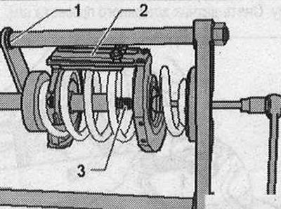
Connect the anti-rotation supports -1- and -2- of both pressure plates to each other using a threaded connection. To do this, lightly tighten the bolts -3- from the add. set Audi Q5 -VAS 6274/11-.
Compressing and unloading the coil springs is only permitted if the two anti-rotation stops -1- and -2- are connected to each other using both bolts -3-. First apply a slight pretension to the thrust plate using the spindle -VAS 6274/10-4-. Check that the coil spring is installed correctly in both pressure plates. When compressing the coil spring, the rotation stop must be located between the lower wishbone and the tie rod. Compress the coil spring using a socket wrench -VAS 6274/6- -3-. If necessary, keep it from turning using the locking button -VAS 6274/7- on the bracket -arrow-.
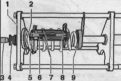
- 1. Thrust plate with lock washer -VAS 6274/11-2-, anti-rotation guard with guide bolts -VAS 6274/11 -6- and spacer -VAS 6274/11 -4-
- 2. Thrust plate with swivel support -VAS 6274/11-1-, rotation guard with longitudinal holes -VAS 6274/11-5- and spacer -VAS 6274/11-4-
- 3. Socket wrench -VAS 6274/6-
Do not use an impact screwdriver to compress the coil spring. Use a standard ratchet wrench to compress the spring.
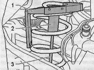
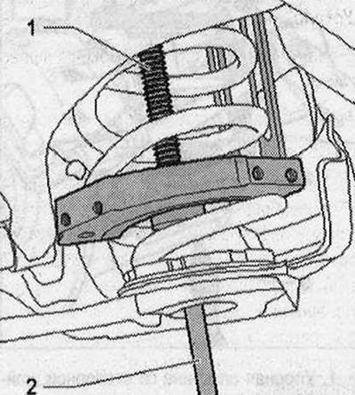
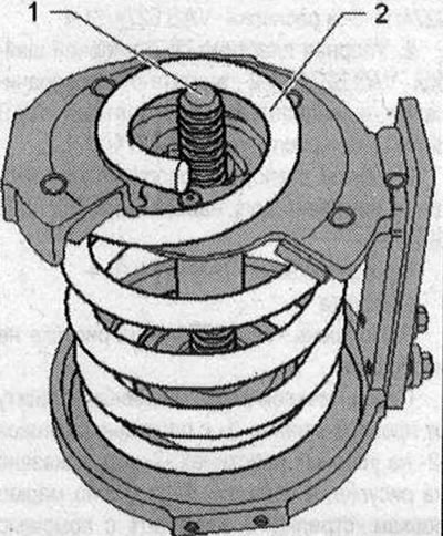
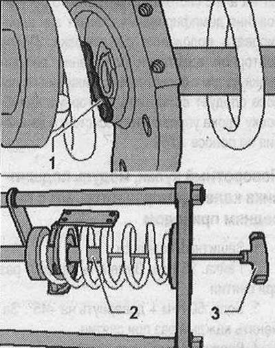
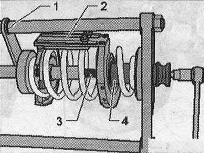
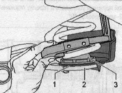
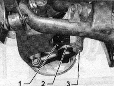
Compress the coil spring -1- until the crankcase guard -3- and the lower spring plate -2- can be removed. If necessary, compress coil spring -1- even more.
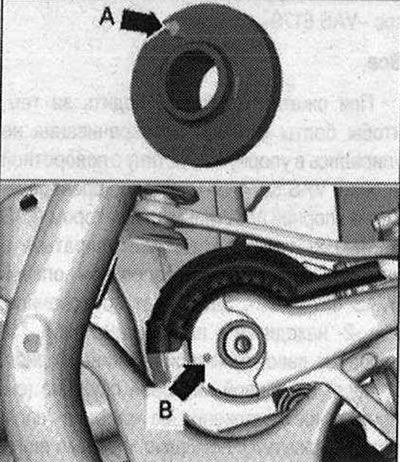
When compressing the spring, make sure that the bolts -arrows A- do not touch the pressure plate stop. The rotation support of the pressure plate -2- must not touch the stop -arrow B- of the pressure plate -1-. Remove the coil spring from below towards the front. If there is not enough space to carry out this stage of work, despite the sufficient pre-compression of the coil spring, it is necessary for an assistant to pull the suspension slightly downwards. The tension on the coil spring may only be relieved using the spring compression system -VAS 6274- and corresponding accessories. Otherwise there is a risk of injury. Relieving the coil spring in the spring compression system -VAS 6274-: If necessary, loosen the spindle -1- (Do not turn completely, risk of injury). The lead screw -1- must not protrude above the end of the coil spring -2-. Install the pre-compressed coil spring into the spring compression system -VAS 6274-.
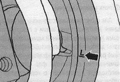
Install a coil spring with left winding on the spring plate -1- so that the stop -2- is opposite the marking "L". Applies only to coil springs on the left side of the vehicle. For coil springs on the right side of the vehicle, the stop -2- must be opposite the marking "R".
Install the lower end of the left spring into the spring compression system -VAS 6274 - near the marking "L" -arrow-. Place the lower end of the right spring in the spring compression system -VAS 6274- near the marking "R".
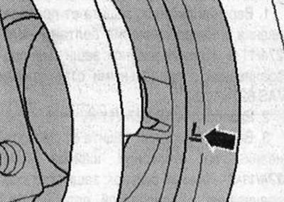
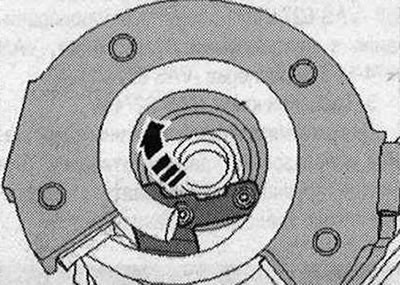
The anti-rotation protection -2- is in position approx. "10 hours" on the left coil spring and approx. "2 hours" on the right coil spring. See the correct position in the right -picture-.
Loosen the coil spring using a socket wrench -VAS 6274/6-. When doing this, release the spring using the spring compressor system -VAS 6274- and the foot pump -VAS 6179-. After removing the load from the coil spring, unscrew the spindle -VAS 6274/10-4- -3-. Unscrew the rotation stop bolts and remove the thrust plate with swivel support -VAS 6274/11 -1 -, the rotation guard with longitudinal holes -VAS 6274/11-5- and the spacer -VAS 6274/11-4-. Move the safety lever-1-back.
Remove piston -VAS 6274/4-2- using T-piece -VAS 6274/5- -3- and remove thrust plate with lock washer -VAS 6274/11- -2-, rotation guard -VAS 6274/11 -6- and spacer -VAS 6274/11-4- made from a coil spring. Fully release the coil spring.
Installation
Install in reverse order. In this case, the following must be taken into account: when compressing coil springs using thrust plates, the lower and upper plates must be installed after 4 turns. Insert the lower part of the coil spring into the spring compression system -VAS 6274-. Support the lower end part (marked with colored dots) left coil spring in spring compression system -VAS 6274- marked "1" -arrow- into the spring plate. Support the lower end part (marked with colored dots) right coil spring in the spring compression system -VAS 6274-marking "R" into the spring plate.
Install thrust plate with lock washer -VAS 6274/11-2-, rotation guard with guide bolts -VAS 6274/11-6- and spacer -VAS 6274/11-4- and insert piston -VAS 6274/4-2- using T-clamp -VAS 6274/5-3-. Secure the position of the piston -2- using the safety lever -1-.
Install thrust plate with swivel support -VAS 6274/11-1-, rotation guard with longitudinal holes -VAS 6274/11 -5- and spacer -VAS 6274/11 - -4-5-. Tighten the anti-rotation bolts -7-. Install spindle -VAS 6274/10-4- -6-. Install the bushing -4- as far as it will go.
For the left coil spring: Lightly tighten the anti-twist bolts -7- by hand. Align the anti-rotation guard with the stop plates in the spring compression system -VAS 6274- so that it is in a position of approx. "10 hours" (see the correct position in the -figure- on the right). Make sure that the end of the coil spring rests against the spring plate -2- with the marking "L". Compress the coil spring using a socket wrench -VAS 6274/6-3-. For compression, use the spring compression system -VAS 6274- and the foot pump -VAS 6179- at the same time.
For the right coil spring: Lightly tighten the anti-twist bolts -7- by hand. Align the anti-rotation guard with the stop plates in the spring compression system -VAS 6274- so that it is in a position of approx. "2 hours" (see the correct position in the -figure- on the left). Make sure that the lower end of the coil spring rests against the spring plate -2- with the marking "R".
Compress the coil spring using a socket wrench -VAS 6274/6--3-. At the same time, use the spring compression system -VAS 6274- and the foot pump-VAS 6179- for compression.
All
When compressing the spring, make sure that the rotation stop bolts do not rest against the thrust plate with the rotary support. VAS 6274/11-1-. The rotation stop of the thrust plate with locking device -VAS 6274/11-2- must also not rest against the thrust plate with rotating support -VAS 6274/11-1-. The anti-rotation protection -2- is in position approx. "10 hours" on the left coil spring and approx. "2 hours" on the right coil spring (see the correct position in the -figure- on the right). When compressing using the spindle -3-, make sure that the bush -4- does not slip out of the pressure plate with articulated support -VAS 6274/11-1-. Loosen spring compression system -VAS 6274 and remove coil spring with spring compressor.
If necessary, compress the coil spring -2- a little more using the spindle -1-. In this case, the lead screw -1 - should protrude above the lead spring -2- only by an amount that still allows the spring plate to be completely placed on top of the spring.
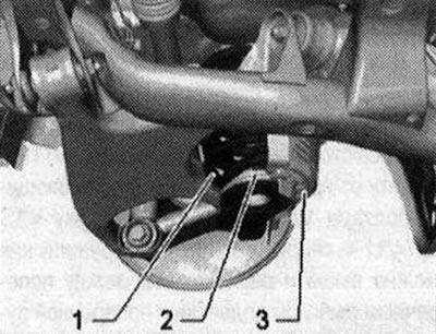
Install the coil spring with spring support -3- and stone guard -1 - onto the steering knuckle -2-. Check that the upper spring plate is installed and install if necessary.
Insert the lower spring support -arrow A- into the hole -arrow B- in the steering knuckle.
Rotate the coil spring -1- until it stops in the spring support -2-.
Then release the coil spring. Tighten the wheel. It is necessary to adjust the wheel alignment angles. On vehicles with electronic damping control, adapting the adjustment position and checking the main headlight adjustments is usually necessary when replacing 1 or both coil springs. After removing and installing the vehicle level sensor or loosening the linkages on vehicles with electronic damping control, the standard suspension position must be re-adjusted. After recalibrating the adjustment position on vehicles with lane assist, the lane departure warning control unit -J759- must be recalibrated.
Visitor comments