
Repair Chevrolet Repair Toyota Repair Honda Repair AvtoVAZ Repair Mercedes-Benz Repair BMW Repair Opel
Home  |  Contacts  |  Sitemap  |    
English Русский
Български
Беларускі
Український
Српски
Hrvatski
Română
Polski
Slovenský
Magyar
AudiManual.ru


  • AUDI 80
  • AUDI 100
  • AUDI A3
  • AUDI A4
  • AUDI A6
  • AUDI A8
  • AUDI Q
  • OTHER
  • ARTICLES
C5 Allroad (1999-2005) C5 (1997-2004) C4 (1994-1997)

General information (Audi A6 C5)

  • Home
  • Audi A6
  • C5 (1997-2004)
  • Power unit
  • Fuel system (diesel)
  • General information
            0
The fuel system is designed to clean and supply atomized fuel to the engine cylinders in the amount required for the corresponding operating mode.

The fuel system includes a rear-mounted fuel tank, fuel filter, high-pressure fuel pump, injectors, high-pressure and low-pressure fuel lines.

Fuel supply devices in diesel engines are much more complex than in petrol engines. Their complexity is determined, first of all, by the fact that it is necessary to inject very small, only a few milligrams, portions of fuel into a high-pressure environment. These portions must be very accurately measured - it is the amount of fuel supplied that controls the operation of the diesel engine. This requires fast-acting and precise injectors. The high compression ratio requires the use of appropriate fuel pumps - the pressure in the injector nozzle must reach several hundred bars. All this complicates and significantly increases the cost of the fuel supply system and, accordingly, the diesel engine itself.

AUDI A6 cars with diesel engines use the electronic engine management system EDC (Electronic Diesel Control) BOSCH, which determines the amount and timing of fuel injection.

The use of an electronic engine management system has the following advantages:
  • the self-diagnostic system allows you to quickly identify defects in the engine. The system has an error memory that records all defects that appeared during engine operation. If the engine malfunctions, the service station can retrieve the errors recorded in the memory using a special device:
  • due to the precise dosage of fuel supplied to the engine in all operating modes, fuel consumption is reduced while maintaining the dynamic characteristics of the vehicle;
  • due to more precise fuel dosing and the use of a catalyst, the emission of harmful substances along with exhaust gases is reduced.

The engine management system components are very reliable and require virtually no maintenance. Maintenance only requires replacing the air and fuel filters. Since complex, expensive equipment is required to check, adjust, and repair the engine management system, this work must be performed at a service station.


No adjustment of the idle speed or governor limited speed is required as part of maintenance.
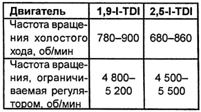
No adjustment of the idle speed or governor limited speed is required as part of maintenance.
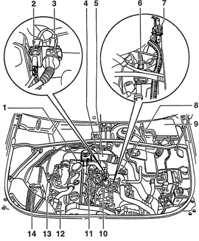

Fig. 4C.1. Location of the EDC engine control system components in the engine compartment with a…

Fig. 4C.1. Location of the EDC engine control system components in the engine compartment with a 1.9-I-TDI engine
1 - air pressure and temperature sensor,
2 - electrical connector of the engine speed sensor,
3 - electrical connector of the fuel injector needle lift sensor,
4 - exhaust gas recirculation valve,
5 - coolant temperature sensor,
6 - fuel pump electrical connector,
8-pin for fuel temperature sensors, fuel injection system fuel metering unit and forced idle speed.

7 - fuel pump electrical connector,
3-pin for engine stop valve and fuel injection timing.

8 - engine speed sensor,
9 - electronic engine control unit with fuses for glow plugs,
10 - fuel pump,
With fuel injection timing valves, engine stop valve and fuel temperature sensor.

11 - fuel injector with needle lift sensor,
12 - boost pressure limiting electromagnetic valve,
13 - exhaust gas recirculation valve,
14 - air flow meter,

Note: The glow plug relay, accelerator pedal position sensor and brake light switch are not shown in the illustration.
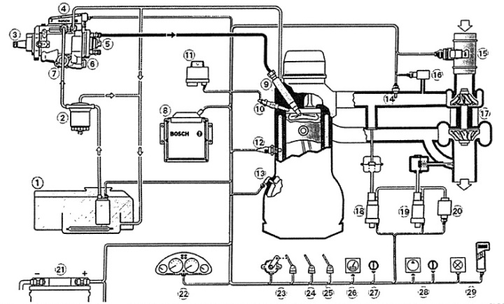

Fig. 4C.2. Diagram of the fuel system of a diesel engine

Fig. 4C.2. Diagram of the fuel system of a diesel engine
1 - fuel tank,
2 - fuel filter,
3 - fuel pump,
4 - fuel pump control unit,
5 - high pressure electromagnetic valve,
6 - fuel injection advance clutch - electromagnetic valve,
7 - fuel injection advance clutch,
8 - engine control unit,
9 - fuel injector,
10 - glow plug,
11 - glow plug control unit,
12 - coolant temperature sensor,
13 - crankshaft speed sensor,
14 - intake air temperature sensor,
15 - air flow meter,
16 - boost pressure sensor,
17 - turbocharger,
18 - exhaust gas recirculation valve,
19 - boost pressure regulator,
20 - low pressure pump,
21 - battery,
22 - instrument cluster,
23 - accelerator pedal position sensor,
24 - clutch switch,
25 - foot brake switch,
26 - speed sensor,
27 - regulator-limiter.
28 - air conditioning compressors,
29 - diagnostic connector.


The original article is located on the online resource AUDIMANUAL.ru
The article was checked by auto expert Alexey Ivanov
This article is available at russian, bulgarian, belarusian, ukrainian, serbian, croatian, romanian, polish, slovak, hungarian

Share information:
Previous articles
Audi A6 C5: Fuel system (diesel)
Next articles

How a diesel engine works
Functioning of the fuel injection system
Fuel heating device
Glow plugs


Link to this page in different formats


Visitor comments

No comments yet


How much will 41 + 28 =


A6(C5 AR, 1999-2005) 
  • General information
  • User manual
  • Maintenance
  • Troubleshooting
  • Power unit
  • V6 petrol engines
  • V8 petrol engines
  • Diesel engines
  • Cooling and heating system
  • Injection system (gasoline)
  • Fuel system (diesel)
  • Supply system
  • Exhaust system
  • Ignition system
  • Transmission
  • Clutch
  • Mechanical gearbox
  • Automatic gearbox
  • Chassis
  • Brake system
  • Car suspension
  • Steering
  • Body
  • Body elements
  • Doors, locks and windows
  • Electrical equipment
  • Equipment and devices
  • Power devices
  • Electrical circuits
  • Schemes (petrol engine 2.7 l)
  • Schemes (petrol engine 4.2 l)
  • Schemes (diesel engine 2.5 l)
 
A6(C5, 1997-2004) 
  • General information
  • User manual
  • Maintenance
  • Power unit
  • Engine repair
  • Cooling system
  • Fuel system
  • Engine management
  • Fuel system (diesel)
  • Exhaust system
  • Transmission
  • Clutch
  • Car gearbox
  • Chassis
  • Front suspension
  • Rear suspension
  • Steering
  • Wheels and tires
  • Brake system
  • Body
  • Exterior
  • Interior
  • Electrical equipment
  • Air conditioner
  • Equipment and devices
  • Electrical circuits
 
A6(C4, 1994-1997) 
  • General information
  • User manual
  • Maintenance (gasoline)
  • Maintenance (Diesel)
  • Gasoline engines
  • 4 cylinder engines
  • 5 cylinder engines
  • 6 cylinder engines
  • Diesel engines
  • 4 cylinder engines
  • 5 cylinder engines
  • Engine repair
  • Removal and reassembly
  • Cooling system
  • Single point injection system
  • Multipoint injection system
  • MPI/MPFI injection system
  • Fuel system (diesel)
  • Exhaust system
  • Ignition system
  • Transmission
  • Clutch
  • Manual transmission
  • Automatic transmission
  • Drive shafts
  • Chassis
  • Brake system
  • Front suspension
  • Rear suspension
  • Steering
  • Body
  • Exterior (external elements)
  • Interior (internal elements)
  • Electrical equipment
  • Power devices
  • Lighting and appliances
  • Electrical circuits
 
AudiManual.ru © 2017-2026 · Mobile version · Feedback · Sitemap: EN BG BY UA RS HR RO PL SK HU · Site search · News and articles
80 B2 · 80 B3 petrol · 80 B3 · 80 B4 · 100 C3 diesel · 100 C3 petrol · 100 C3 · 100 C4 petrol · 100 C4 · A3 Type 8L · A4 B5 petrol · A4 B5 · A4 B6 petrol · A4 B6 · A4 B7 · A4 B8 · A6 C4 · A6 C5 · A6 C5 Allroad · A8 D2 · Q5 Type 8R · Q7 Typ 4L · Audi A2 ·
This site uses cookies 🍪. Click the button to accept this fact.