
Table of contents: Removal ↓ Installation ↓
The gearbox can be removed without removing the engine.
Removing the gearbox is necessary when replacing the clutch or when repairing or overhauling the gearbox. We do not recommend repairing the gearbox yourself. The car owner can dismantle the faulty gearbox himself and deliver it to the workshop.
To remove the gearbox, the vehicle must be raised to a sufficient height.
Removal
1. Disconnect the negative (-) battery terminal from the battery.
Cars with V-shaped six-cylinder petrol engine (biturbo)
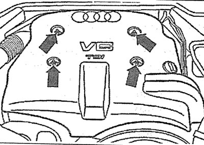
2. Unscrew the bolts securing the protective cover above the engine and remove it (see arrows in the illustration).
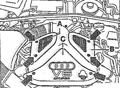
2.2. Unscrew the bolts securing the protective cover above the engine and remove it (see arrows)
Attention! The protective cover consists of three parts (see A, B and C in Illustration 2.2).
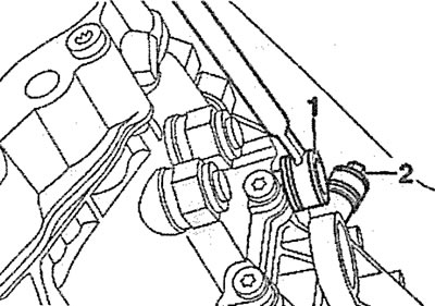
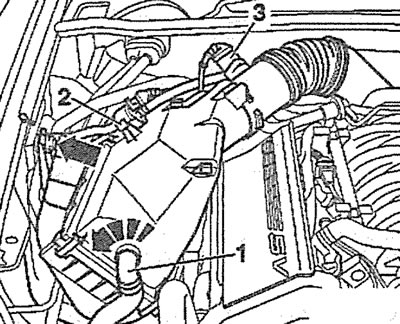
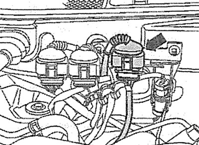
3 Remove the supply air duct by disconnecting the canister purge hose 1 from it, unscrewing the bolts 3 and loosening the clamps 2 (see illustration).
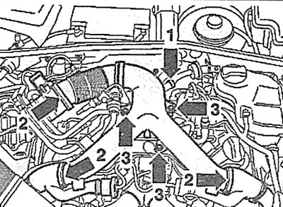
2.3. Remove the supply air duct by disconnecting the canister purge hose 1 from it, unscrewing the bolts 3 and loosening the clamps 2
4. Unscrew the mounting bolts of the expansion tank of the cooling system and move it to the side without disconnecting the hoses, see the corresponding chapter.
5. Disconnect the plugs 1 of the lambda probes on the exhaust manifolds of the right and left heads and release their wires from the holders (see illustration).
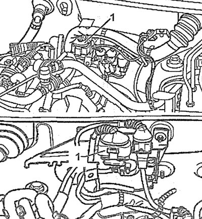
2.5. Disconnect the plugs 1 of the lambda probes on the exhaust manifolds of the right and left heads
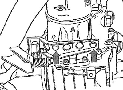
6. Unscrew both bolts 2 securing the heat shield above the right and left intake pipes (see illustration).
2.6. Unscrew both bolts 2 securing the heat shield above the right and left intake pipes
7. Unscrew nuts 3, fastenings of the right and left intake pipes, and also unscrew the upper bolts with which the gearbox is connected to the engine (see illustration 2.6).
8. Place the car on jack stands and remove the engine compartment protection (see arrows in the illustration).
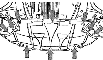
2.8. Remove the engine compartment protection (see arrows)
9. Unscrew the bolts and remove the engine compartment protection bracket (see arrow in illustration).
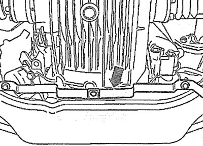
2.9. Unscrew the bolts and remove the engine compartment protection bracket (see arrow)
10. Unscrew the bolts and detach the protective shields above the right and left drive shafts from the gearbox (see arrows in the illustration), and then unscrew the bolts and disconnect the right and left drive shafts 1 from the box.
2.10. Unscrew the bolts and disconnect the protective shields above the right and left drive shafts from the gearbox (see arrows)
11. Loosen the clamps/couplings on the exhaust system and move the clamps onto the pipes.
12. Unscrew the bolts and remove the protective shield above the propeller shaft (see arrows in the illustration).
2.12. Unscrew the bolts and remove the protective shield above the propeller shaft (see arrows)
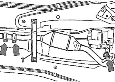
13. Unscrew the bolts securing the propeller shaft 1 to the gearbox, lower it onto the shield 2 and additionally secure it with wire to the holder 3 of the fuel lines (see illustration).
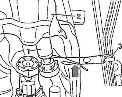
2.13. Unscrew the bolts securing the propeller shaft 1 to the gearbox, lower it onto the shield 2 and additionally secure it with wire to the holder 3 of the fuel lines
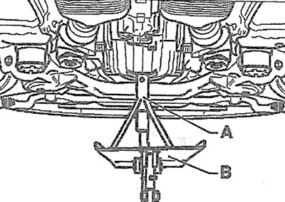
14. Unscrew the bolts (see arrows in the illustration), which secure crossbar A to the bottom, and remove it.
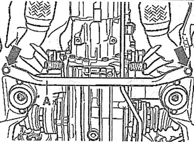
2.14. Unscrew the bolts (see arrows), which secure the crossbar A to the bottom, and remove it
15. Unscrew bolts 4 and 5 and remove brackets B, which hold the exhaust pipes (see illustration).
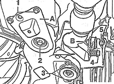
2.15. Unscrew bolts 4 and 5 and remove brackets B, which hold the exhaust pipes
16. Place a suitable support under the gearbox.
17. Unscrew bolts 1 and 2 of the left and right connecting brackets A of the subframe and remove the brackets (see illustration 2.15).
18. Lower the rear of the subframe down by approximately 50 mm (see "a" in the illustration) and insert a wooden wedge between the subframe and the power block.
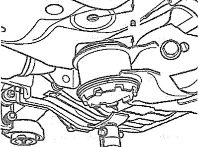
2.18. Lower the rear part of the subframe down by approximately 50 mm (see "a")
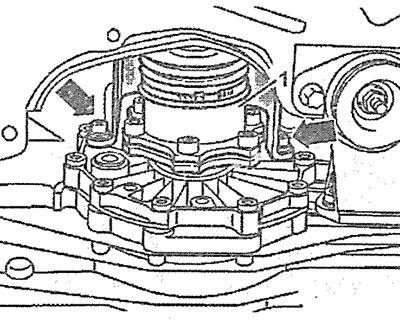
19. Unscrew bolts 1 and 2 and remove the right and left gearbox supports (see illustration).
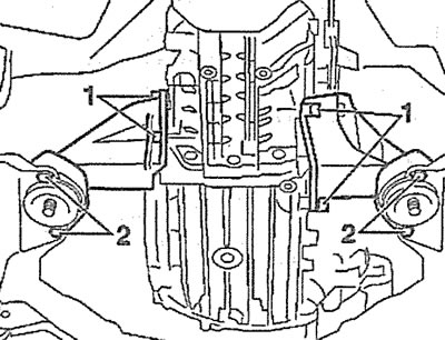
2.19. Unscrew bolts 1 and 2 and remove the right and left gearbox supports
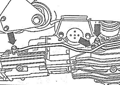
20. Loosen clamp 3, lift shield 2 and unscrew lower nuts 5 securing the inlet pipe to the exhaust manifold (see illustration).
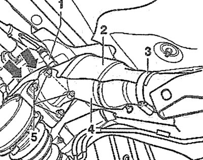
2.20. Loosen clamp 3, lift shield 2 and unscrew lower nuts 5 securing the intake pipe to the exhaust manifold
21. Lift shield 2 upwards and disconnect the inlet pipe with catalytic converter 4 from the exhaust manifold (see illustration 2.20).
Caution! Make sure that when disconnecting the pipe, the lambda probe 1 passes through the cutout in the shield 2 (see illustration 2.20).
Attention! Do not bend the flexible connecting element of the intake pipe at an angle greater than 10°. Otherwise, this element will be damaged.
22. Raise the gearbox slightly upwards with the support installed under it to relieve the two lower M10x60 bolts with Allen key heads securing the gearbox to the engine and unscrew them (see arrows in the illustration).
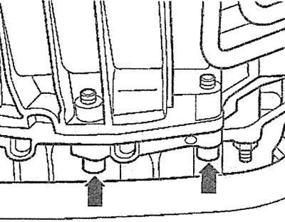
2.22. Unscrew the two lower bolts securing the gearbox to the engine (see arrows)
Attention! When installing the gearbox, replace these bolts with new M10x55 hexagon-head bolts to ensure the required tightening torque.
23. Lower the gearbox down on the support.
24. Unscrew the tachometer sensor mounting bolt on the left side of the gearbox and move the sensor to the side (see arrow in illustration).
2.24. Unscrew the tachometer sensor mounting bolt and move the sensor to the side (see arrow)
25. Disconnect the speedometer sensor and reverse light switch connector.
26. Unscrew the starter mounting bolts and move it forward as far as possible without disconnecting the wires from it.
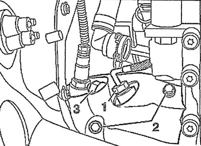
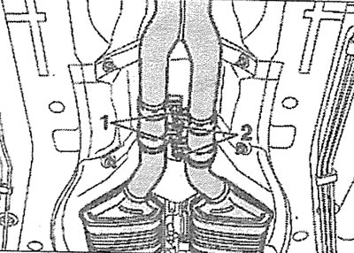
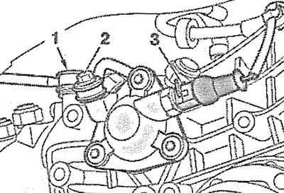
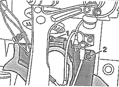
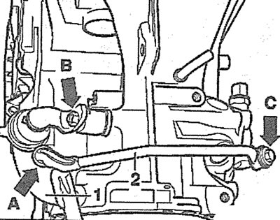
27. Unscrew the connecting bolt 2 of the gearshift rod on the right side of the gearbox, as well as the bolt 1 with a hexagonal socket head securing the rod (see illustration).
2.27. Unscrew the connecting bolt 2 of the gear shift rod, as well as the bolt 1 with a head for a hexagonal socket wrench for fastening the rod
28. Unscrew nut 1 and remove lever 2 of the gear shift rod from the rod (see illustration).
2.28. Unscrew nut 1 and remove lever 2 of the gear shift rod from the rod
29. Remove all remaining lower transmission-to-engine mounting bolts, leaving only two bolts.
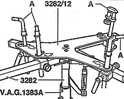
2.29. VAG 1383A support for removing the gearbox with A mounts and adjustment plate 3282/12
Attention! The car manufacturer recommends that at this stage, in order to remove the gearbox, you install a special support with appropriate fasteners and a so-called adjustment plate under it (see illustration 2.29). If there is no such support, the gearbox should be securely fastened to the already installed support in order to use it to remove the gearbox from under the car.
30. Make sure all wires, hoses and other connections on the transmission are disconnected and will not be damaged when lowering the transmission from the engine compartment.
31. Remove the two remaining bolts securing the gearbox to the engine and lower the gearbox down enough to access the clutch slave cylinder.
Caution: This operation must be performed carefully to avoid damaging the cylinder line.
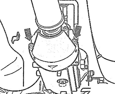
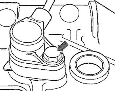
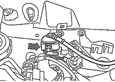
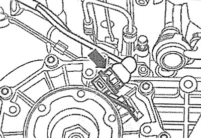
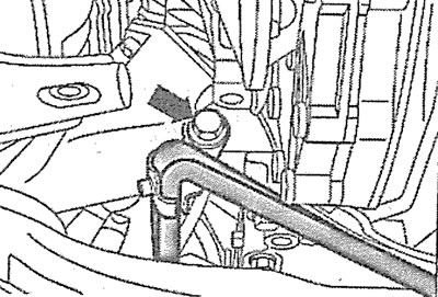
32. Unscrew the clutch slave cylinder mounting bolt (see arrow in illustration) and move the cylinder back without disconnecting the pipeline from it.
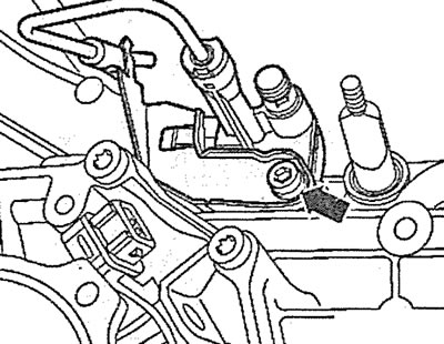
2.32. Unscrew the clutch slave cylinder mounting bolt (see arrow) and move the cylinder back
33. Disconnect the engine and gearbox, lower the gearbox down on the support and remove it from under the car.
Cars with V8 petrol engine
34. Unscrew the bolts (see arrows in the illustration) fastenings of expansion tank 3 of the cooling system, disconnect the plug of the coolant level sensor and move the tank to the side without disconnecting hoses 1 and 2 from it.
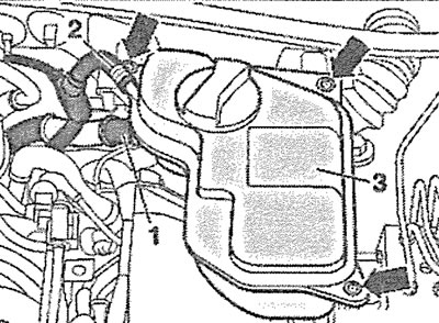
2.34. Unscrew the bolts (see arrows) expansion tank 3 fastenings of the cooling system, disconnect the coolant level sensor plug and move the tank to the side
35. Release the lambda probe plug on the exhaust manifold of the left cylinder head from the holder and disconnect it (see arrow in illustration). Move the wires down.
2.35. Release the lambda probe plug on the exhaust manifold of the left cylinder head from the holder and disconnect it (see arrow)
36. Unscrew the nuts securing the intake pipes to the exhaust manifolds, accessible from the top of the engine compartment.
37. Unscrew the bolts securing the air intake 1 to the upper front cross member (see arrows in the illustration), disconnect the air intake and remove the air filter cover.
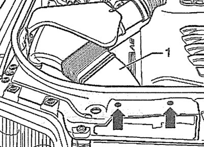
2.37. Unscrew the bolts securing the air intake 1 to the upper front crossmember (see arrows)
38. Disconnect plug 3 of the mass air flow sensor and release valve 2 of the adsorber purge from the holder on the air filter housing (see illustration).
2.33. Disconnect plug 3 of the mass air flow sensor and release valve 2 of the adsorber purge from the holder
39. Disconnect the afterburner hose 1 from the air filter housing by turning the fitting counterclockwise (see illustration 2.38).
40. Disconnect the air supply duct from the throttle valve and the low pressure hose from the right side of the engine.
41. Unscrew the bolt (see arrow in illustration 2.38)fasten the air filter housing to the body and remove it.
42. Release the lambda probe plug on the exhaust manifold of the right cylinder head from the holder and disconnect it (see arrow in illustration). Move the wires down.
2.42. Release the lambda probe plug on the exhaust manifold of the right cylinder head from the holder and disconnect it (see arrow)
43. Place the vehicle on jack stands and remove the engine compartment guard and the guard mounting bracket (see illustrations 2.8 and 2.9).
44. Unscrew the bolts and disconnect the protective shields above the right and left drive shafts from the gearbox, and then unscrew the bolts and disconnect the right and left drive shafts from the gearbox 1 (see illustration 2.10). Tie the drive shafts to the body with wire so that they do not sag.
45. Unscrew the nuts securing the exhaust manifolds to the left and right cylinder heads of the inlet pipes (see arrows in the illustration).
2.45. Unscrew the nuts securing the exhaust manifolds to the left and right cylinder heads of the inlet pipes (see arrows)
46. Unscrew bolts 1 and 2 securing the brackets of the inlet pipes to the gearbox and disconnect the inlet pipes from the exhaust manifolds (see illustration).
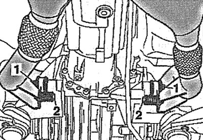
2.46. Unscrew bolts 1 and 2 securing the brackets of the inlet pipes to the gearbox
Attention! Bending the flexible connecting element of the intake pipe by more than 10° is not allowed.
47. Loosen bolts 1 and 2 of the connecting clamps/couplings on the exhaust pipes, move them back and remove the inlet pipes with catalytic converters and lambda probes (see illustration).
2.47. Loosen bolts 1 and 2 of the connecting clamps/couplings on the exhaust pipes and remove the inlet pipes
48. Unscrew the bolts and remove the protective shield above the propeller shaft (see arrows in illustration 2.12).
49. Unscrew the bolts securing the propeller shaft 1 to the gearbox, lower it onto the shield 2 and additionally secure it with wire to the holder 3 of the fuel lines (see illustration 2.13).
50. Place a suitable support under the gearbox and lift it slightly to relieve the load on its suspension supports (see illustration).
2.50. Place a suitable support under the gearbox and lift it slightly to relieve the load on its suspension supports
51. Unscrew bolts 1 and 2 and remove the right and left gearbox supports (see illustration 2.19).
52. Raise the gearbox a little more and unscrew the two lower bolts securing the gearbox to the engine (see illustration 2.22).
53. Lower the gearbox down to its original level and unscrew all the bolts connecting the gearbox to the engine, leaving only two for safety.
54. Unscrew the connecting bolt 2 of the gear shift rod and the bolt 1 with a head for an 8 mm Allen key of the rod mount, and also disconnect the plug 3 of the reverse light switch (see illustration).
2.54. Unscrew connecting bolt 2 of the gear shift rod and bolt 1 of the rod mount using a socket head
55. Remove the protective shield over the tachometer/crankshaft position sensor, unscrew the mounting bolt, remove the sensor and move it to the side (see illustration 2.24). The sensor is located on the left side of the gearbox.
56. Disconnect the speedometer sensor connector (see arrow in illustration).
2.56. Disconnect the speedometer sensor plug (see arrow)
57. Unscrew nut 1 and remove lever 2 of the gear shift rod from the rod (see illustration 2.28).
58. Unscrew the clutch slave cylinder mounting bolt (see arrow in illustration 2.32) and move the cylinder back without disconnecting the pipeline from it.
59. Unscrew the mounting bolts and disconnect the transmission fluid pipes from the gearbox (see arrows in the illustration). Seal the pipe openings with suitable plugs.
2.59. Unscrew the mounting bolts and disconnect the transmission fluid pipes from the gearbox (see arrows)
60. Unscrew the pipeline holder bolt (see arrow in illustration), move the pipes to the right and secure them to the body with wire.
2.60. Unscrew the pipeline holder bolt (see arrow) and move the pipelines to the right
61. Unscrew the remaining two bolts securing the gearbox to the engine, separate the engine and gearbox, lower the gearbox down on the support and remove it from under the car.
Cars with V6 TDI diesel engine
Attention! To access the bolts that secure the gearbox to the engine, it is necessary to remove the intake pipe with the catalytic converter.
62. Remove the engine protective cover by unscrewing the mounting bolts (see arrows in the illustration).
2.62. Remove the engine protective cover by unscrewing the mounting bolts (see arrows)
63. Unscrew the bolts and remove the protective shield above the turbocharger (see arrows in the illustration).
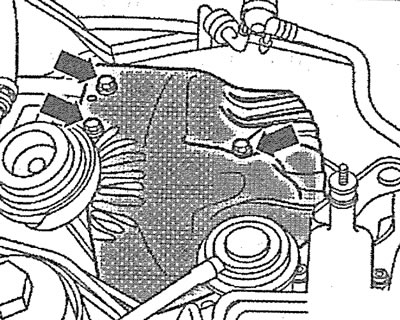
2.63. Unscrew the bolts and remove the protective shield above the turbocharger (see, arrows)
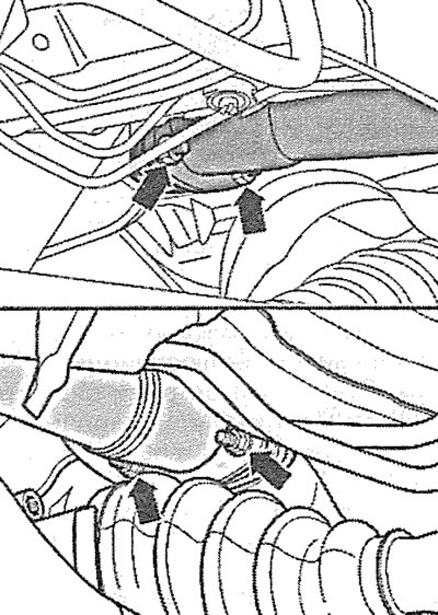
64. Unscrew the bolts securing the inlet pipe to the turbocharger (see arrows in the illustration).
2.64. Unscrew the bolts securing the inlet pipe to the turbocharger (see rags)
65. Place the vehicle on jack stands and remove the engine guard.
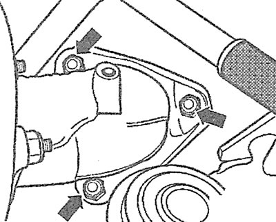
66. Unscrew the bracket mounting bolts A (see arrows in the illustration).
2.66. Unscrew the bracket mounting bolts A (see arrows)
67. Remove cross member 1, loosen the bolts of the connecting clamp (see arrows in the illustration) and remove the exhaust pipe.
2.67. Remove cross member 1, loosen the bolts of the connecting clamp (see arrows) and remove the intake pipe
68. Unscrew the upper bolts securing the gearbox to the engine.
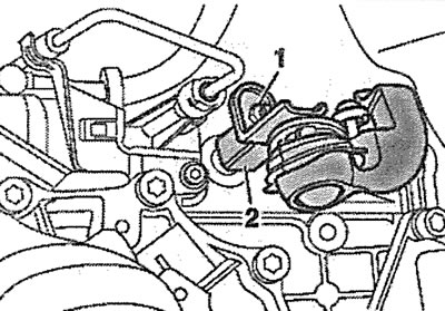
69. Loosen bolt A located behind the turbocharger and move bracket B in the direction of the arrow (see illustration). After this, tighten bolt A.
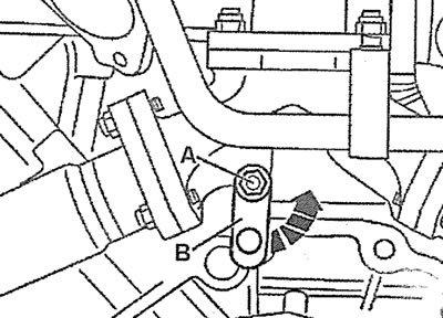
2.69. Loosen bolt A and move bracket B in the direction of the arrow
70. Unscrew bolt 2, which secures the shield above the left drive shaft, disengage grip 1 of the shield and remove the shield (see illustration).
2.70. Remove the shield above the left drive shaft by unscrewing bolt 2
71. Unscrew the bolts and disconnect the protective shields above the right and left drive shafts from the gearbox (see arrows in illustration 2.10), and then unscrew the bolts and disconnect the right and left drive shafts 1 from the box. Tie the shafts to the body with wire so that they do not sag.
72. Unscrew the tachometer sensor mounting bolt on the left side of the gearbox and move the sensor to the side (see arrow in illustration 2.24).
73. Disconnect the speedometer sensor and reverse light switch plug. Release the sensor wires from the holder on the gearbox.
74. Unscrew the starter mounting bolts and move it forward as far as possible without disconnecting the wires from it.
75. Unscrew all the bolts securing the gearbox to the engine, leaving only one for safety.
76. Unscrew the connecting bolt 2 of the gearshift rod on the right side of the gearbox, as well as the bolt 1 with a hexagonal socket head securing the rod (see illustration 2.27).
Caution! Do not remove the ball head when unscrewing the connecting rod 2 (see arrow A in illustration 2.78) from the 1 gearshift rod if the connecting rod is not set to approximately the 11 o'clock position. The ball head is damaged when removed.
77. Unscrew nut B and unscrew bolt C to remove the gear shift rod (see illustration).
2.77. Unscrew nut B and unscrew bolt C to remove the gear shift rod
78. Unscrew nut 1 and remove lever 2 of the gear shift rod from the rod (see illustration 2.28).
79. Unscrew the bolts and remove the protective shield above the propeller shaft (see arrows in illustration 2.12).
80. Unscrew the bolts securing the propeller shaft 1 to the gearbox, lower it onto the shield 2 and additionally secure it with wire to the holder 3 of the fuel lines (see illustration 2.13).
81. Unscrew bolts 1 and 2 and remove the right and left gearbox supports (see illustration 2.19).
82. Unscrew the remaining bolt securing the gearbox to the engine, move the gearbox off the mounting bushings on the engine and lower the gearbox on the support down so that the clutch slave cylinder becomes accessible.
Caution: This operation must be performed carefully to avoid damaging the cylinder line.
83. Unscrew the clutch slave cylinder mounting bolt (see arrow in illustration 2.32) and move the cylinder back without disconnecting the pipeline from it.
84. Disconnect the engine and gearbox, lower the gearbox down on the support and remove it from under the car.
Installation
85. Before installing the gearbox, check the condition of the clutch pressure and driven discs.
86. Clean off any corrosion and apply a thin layer of molybdenum grease or AUDI-G 000100 grease to the spline of the driven disk hub and also to the gear ring of the gearbox input shaft.
Caution! The clutch disc must move easily on the input shaft. Excess grease must be removed.
87. Check the condition of the clutch release bearing and replace it if necessary
88. Check for the presence of centering pins for the gearbox on the engine. Install the pins if necessary.
89. Install the gearbox on a support under the engine compartment, lift it and insert the gearbox input shaft into the splined hole of the driven clutch disc, holding the gearbox horizontally. If the splines of the driven disc hub and the input shaft do not match, turn the shaft by hand using the flange.
90. Install the clutch slave cylinder in place and press it together with the pipe holder with a crowbar until the mounting bolt can be screwed in.
91. Install the starter and screw in the upper bolts securing the box to the engine (see illustrations 2.91, 2.91a and 2.91b).
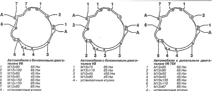
2.91. Tightening torques for gearbox-to-engine mounting bolts
92. Install and tighten the three lower engine and gearbox mounting bolts
93. Install and secure the drive shafts.
94. Install the right and left drive shaft protective shields in place by tightening the bolts to a torque of 20 Nm.
95. Connect and bolt the shift rod and the gearshift shaft to the gearbox.
96. Connect the plugs of the speedometer sensor and the reverse light switch.
97. Connect the exhaust pipe.
98. Check the transmission fluid level in the gearbox.
99. Adjust the gear shift mechanism.
100. Reinstall the engine splash guard holder.
101. Reinstall the mudguard.