
The generator power is indicated on the nameplate.
Attention! If additional electrical equipment is installed, it is necessary to check whether the existing generator has sufficient power. If necessary, install a more powerful generator.
The generator produces alternating current, but since the battery can only be charged with direct current, the three-phase current is converted into direct current by a rectifier located on the diode board. The voltage regulator changes the charging current according to the degree of discharge of the battery by switching the excitation current on and off.
At the same time, the voltage regulator maintains a constant operating voltage (about 14V), regardless of the generator rotation speed.
When working on a generator, there are certain requirements that must be followed to prevent damage to the electrical system.
Before starting work on the electrical system, be sure to disconnect the negative (-) battery terminal from the battery.
Attention! This will delete the recorded information from some devices, and the security code from the radio receiver, as well as all automatic settings for radio stations. Therefore, before disconnecting the battery, the access code should be clarified and written down. Otherwise, the radio receiver can only be put into operation with the help of a representative of the manufacturer or an AUDI workshop. It is also recommended to write down the radio receiver settings for radio stations.
Do not disconnect the battery or voltage regulator while the engine is running.
Do not remove the generator while the battery is connected.
Disconnect the battery when performing welding work on the vehicle.
Removal
1. Disconnect the negative (-) battery terminal from the battery.
2. Drain the coolant.
3. Remove the front bumper (see the relevant chapter).
Cars with 8-cylinder petrol engine
4. Set the upper front cross member to the service position.
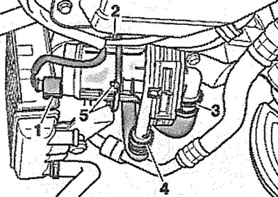
5. Disconnect plug 3 from the solenoid valve 2 for purging the adsorber and carefully remove the valve from the holder (see illustration).
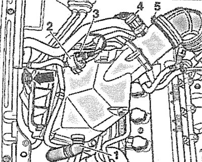
10.5. Disconnect plug 3 from the solenoid valve 2 for purging the adsorber. Cars with a petrol 8-cylinder engine
6. Disconnect plug 4 of the mass air flow sensor (see illustration 10.5).
7. Carefully disconnect hose 1 of the afterburning system pump (see illustration 10.5).
8. Disconnect the air duct by loosening the clamp 5 (see illustration 10.5).
9. Unscrew the bolt (see arrow in illustration 10.5) and remove the air filter housing.
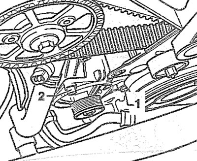
10. Disconnect the coolant hoses by loosening clamps 1 and 2 (see illustration).
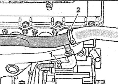
10.10. Disconnect the coolant hoses by loosening clamps 1 and 2 (in the illustration the engine is removed). Cars with 8-cylinder petrol engine
11. Place a tray or suitable container under the engine to collect any remaining coolant.
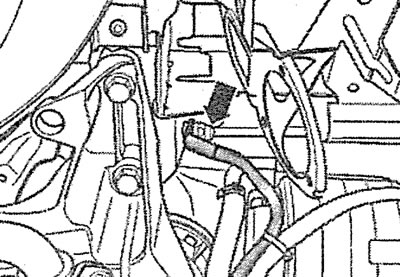
12. Disconnect the coolant hose going to the oil radiator by removing the mounting clamp (see arrow in illustration).
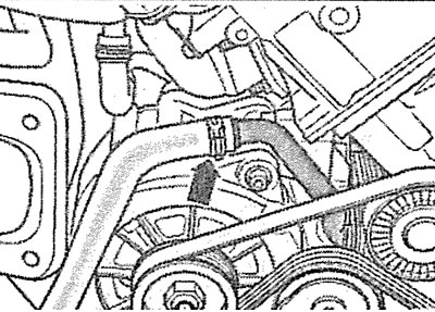
10.12. Disconnect the coolant hose going to the oil radiator by removing the mounting clamp (see arrow). Cars with 8-cylinder petrol engine
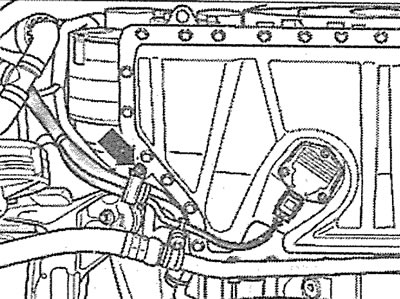
13. Disconnect the cooling system hoses by loosening the corresponding fastening clamps (see arrows in the illustration).
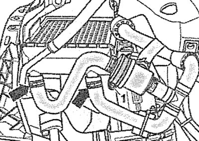
10.13. Disconnect the cooling system hoses by loosening the corresponding fastening clamps (see arrows). Cars with 8-cylinder petrol engine
14. Remove clamp 1 securing the coolant hose to the thermostat housing (see illustration 10.13) and remove the hose. Move the remaining coolant hoses away from the work area.
15. Cars with an afterburning system. Disconnect the hoses from the afterburning system pump housing by loosening the clamps 3 and 4 (see illustration).
10.15. Disconnect the hoses from the afterburning system pump housing by loosening the clamps 3 and 4. Cars with an 8-cylinder engine and an afterburning system
16. Cars with an afterburning system. Disconnect plug 1, unscrew nuts 2 and 5 and remove the afterburning system pump from the bracket (see illustration 10.15).
17. Unscrew the nut (see arrow) and disconnect the ground (-) wire terminal from the side member (see illustration).
10.17. Unscrew the nut and disconnect the terminal of the ground (-) wire from the side member. Cars with a gasoline 8-cylinder engine
18. Unscrew the bolt (see arrow in illustration) holder with which the oil line is attached to the bottom of the oil pan.
10.18. Unscrew the bolt (see arrow) bracket that secures the oil line to the bottom of the oil pan. Cars with a gasoline 8-cylinder engine
19. Unscrew the bolt (see arrow in illustration) and carefully remove the V-belt of the generator drive (see the relevant chapter).
10.19. Unscrew the bolt (see arrow) and carefully remove the V-belt of the generator drive. Cars with a gasoline 8-cylinder engine
Caution! Before removing, mark the direction of rotation of the V-belt of the generator drive. If the old belt is installed against the direction of its rotation, this will lead to its premature wear and tear.
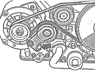
20. Unscrew the bolts (see arrows in the illustration)fasteners and remove the generator drive belt tensioner.
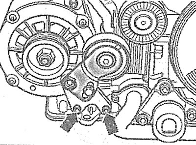
10.20. Unscrew the bolts (see arrows) fasteners and remove the alternator drive belt tensioner. Cars with a gasoline 8-cylinder engine
21. Unscrew the bolts (see arrows in the illustration) generator mounts.
10.21. Unscrew the bolts (see arrows) generator mounts. Cars with petrol 8-cylinder engine
Caution: If the generator is clamped in the bracket, screw in the generator mounting bolts again by about two turns and gently tap the bolt heads with a hammer to unlock the generator mounting bolt bushings.
22. Disconnect the coolant hose from the generator by removing clamp 3, disconnect plug 1, unscrew nut 2 of the generator wire terminal (see illustration) and carefully remove the generator.
10.22. Disconnect the coolant hose from the generator by removing clamp 3, disconnect plug 1, unscrew nut 2 of the generator wire terminal. Cars with a gasoline 8-cylinder engine
Cars with a 6-cylinder petrol engine
23. Remove the accessory drive V-belt from the alternator pulley (see the relevant chapter).
24. Loosen clamps 1 and remove hose 2 going to the intercooler (see illustration).
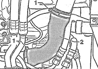
10.24. Loosen clamps 1 and remove hose 2 going to the intercooler. Cars with a petrol 6-cylinder engine
25. Disconnect the wire connected to the 30/V+ terminal of the generator by unscrewing the nut 2 of the terminal (see illustration).
10.25. Disconnect the wire connected to the 30/V+ terminal of the generator by unscrewing the nut 2 of the terminal. Cars with a petrol 6-cylinder engine
26. Disconnect the wire from terminal 1 D+ of the generator by unscrewing the corresponding nut (see illustration 10.25).
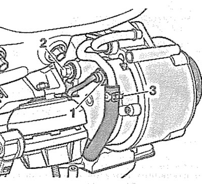
27. Cars with automatic transmission. Unscrew nut 1 of the transmission fluid circulation pipe holder (see illustration).
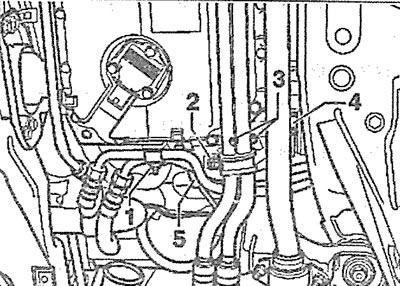
10.27. Unscrew nut 1 of the transmission fluid circulation pipe holder. Cars with a 6-cylinder petrol engine and automatic transmission
28. Unscrew nut 2 of the refrigerant circulation pipe holder, then unscrew bolts 3, loosen clamp 4 and disconnect pipe 5 (see illustration 10.27).
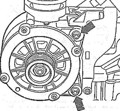
29. Unscrew the generator mounting bolts 1 and 2 and carefully remove the generator by pushing it downwards (see illustration).
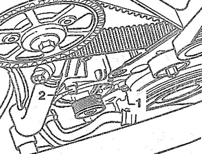
10.29. Unscrew generator mounting bolts 1 and 2. Cars with a 6-cylinder petrol engine
Caution: If the generator is clamped in the bracket, screw in the generator mounting bolts again by about two turns and gently tap the bolt heads with a hammer to unlock the generator mounting bolt bushings.
Diesel Engine Cars
30. Remove the air filter cover 2 together with the air intake 1 (see illustration).
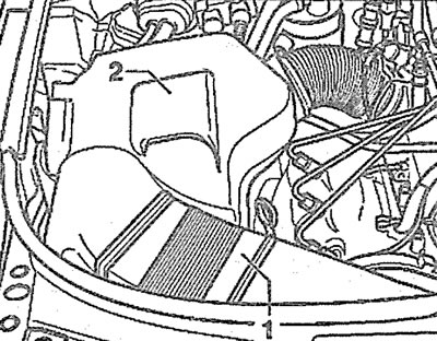
10.30. Remove the air filter cover 2 together with the air intake 1. Vehicles with a diesel engine
31. Unscrew the bolts (see arrows in the illustration) fasteners and remove the upper protective engine cover.
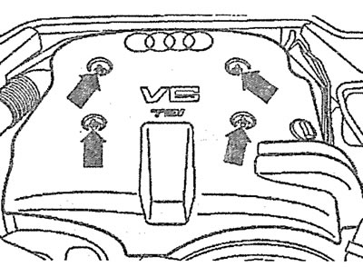
10.31. Unscrew the bolts (see arrows) fasteners and remove the upper engine cover. Vehicles with a diesel engine
32. Cars with parking heater. Unscrew the bolts (see arrows in the illustration) fastening the parking heater pipe to the soundproofing shield.
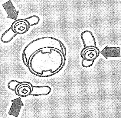
10.32. Unscrew the bolts (see arrows) fastening the parking heater pipe to the soundproofing shield. Cars with a diesel engine and parking heater
33. Unscrew the bolts and press the clamps 1-3 and 5 and remove the engine splash guard (see illustration).
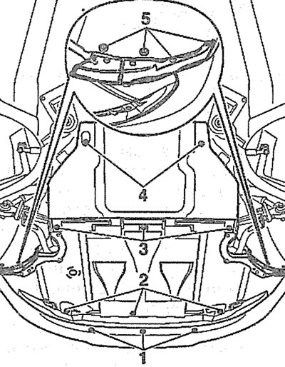
10.33. Unscrew bolts/press fasteners 1-3 and 5 and remove the engine splash guard. Vehicles with a diesel engine
34. Remove the front bumper (see the relevant chapter).
35. Remove the auxiliary drive V-belt from the alternator pulley (see the relevant chapter).
36. Disconnect the wire from terminal 1 30/V+ of the generator by unscrewing the corresponding fastening nut (see illustration).
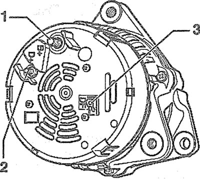
10.36. Disconnect the wire from terminal 1 30/V+ of the generator by unscrewing the corresponding fastening nut. Vehicles with a diesel engine
37 Disconnect the wire from terminal 2 D+ of the generator by unscrewing the corresponding fastening nut (see illustration 10.36).
38. Disconnect the plug from terminal 3 DF (see illustration 10.36).
39. Unscrew generator mounting bolts 1 and 2 (see illustration).
10.39. Unscrew generator mounting bolts 1 and 2. Vehicles with diesel engines
Caution: If the generator is clamped in the bracket, screw in the generator mounting bolts again by about two turns and gently tap the bolt heads with a hammer to unlock the generator mounting bolt bushings.
40. Disconnect the plug (see arrow in illustration) hydraulic engine support and remove the generator by pushing it down.
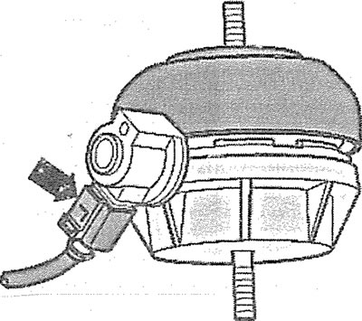
10.40. Disconnect the plug (see arrow) hydraulic engine mount and remove the generator
Installation
The generator is installed in the reverse order of removal.
Generator carbon brushes - check
41. Remove the voltage regulator (see the relevant chapter).
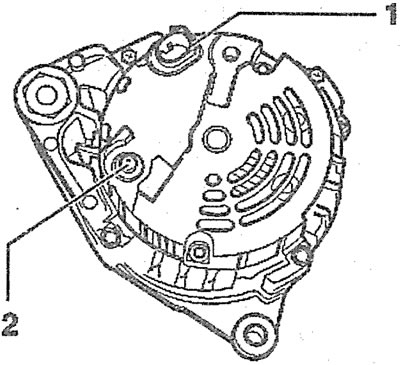
42. Measure the length "a" of the generator brushes (see illustrations 10.42 and 10.42a). The permissible residual length of the brushes is 5 mm.
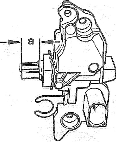
10.42. Measure the length "a" of the generator brushes. Bosch Generator |
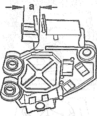
10.42a. Measure the length "a" of the generator brushes. Valeo generator |