
Table of contents: Removal ↓ Installation ↓
The starter consists of a drive housing, an anchor housing, and a collector housing. The anchor and collector, as well as the brush holder, are located in the anchor housing and in the collector housing. The brush holder contains carbon brushes, which, although slowly, still gradually wear out. If the carbon brushes are heavily worn out, the starter cannot operate flawlessly.
The drive housing contains a gear drive. If voltage is supplied to the starter through the ignition switch, the traction relay located in the starter housing pushes the gear along the steep thread to the flywheel ring gear. As soon as the gear reaches the stop against the spindle, a mechanical connection with the flywheel occurs. Now the starter can bring the engine to the required speed. If the engine starts, the gear is accelerated by the engine. For some time, it rotates faster than the starter and disengages, which leads to the termination of the connection between the starter and the engine.
Since a large current is required to start an internal combustion engine, the condition of the wire connections should be checked during vehicle maintenance. Rusted contacts should be cleaned and lubricated with a protective grease used to protect battery terminals.
Attention! The procedure is given using the example of cars with a gasoline 8-cylinder engine without turbocharging.
Removal
1. Disconnect the negative (-) battery terminal from the battery.
Attention! If the radio has an access code, then disconnecting the battery deletes this code. After connecting the battery, the radio can only be turned on after entering the appropriate code or by using the services of an AUDI workshop or the manufacturer of the radio. Therefore, before disconnecting the battery, check and write down the entered code.
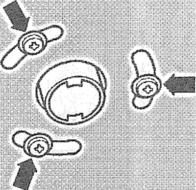
2. Remove the engine protective cover (see arrows in the illustration).
12.2. Remove the engine protective cover (see arrows)
Attention! If the radio has an access code, then disconnecting the battery deletes this code. After connecting the battery, the radio can only be turned on after entering the appropriate code or by using the services of an AUDI workshop or the manufacturer of the radio. Therefore, before disconnecting the battery, check and write down the entered code.
Attention! To remove the starter, it is necessary to unload the power unit supports, for which lift the engine and gearbox using a lift, hoist or crossbar, which is secured above the engine compartment (see illustration 12.0).
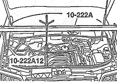
12.0. Install a cross beam on the front to relieve the load on the power unit supports
3. Cars with parking heater. Unscrew the bolts (see arrows in the illustration) fastening the parking heater pipe to the soundproofing shield.
12.3. Unscrew the bolts (see arrows) fastening the parking heater pipe to the soundproofing shield. Cars with a diesel engine and parking heater
4. Unscrew bolts/press fasteners 1-3 and 5 and remove the engine splash guard (see illustration).
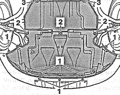
12.4. Unscrew bolts/press fasteners 1-3 and 5 and remove the engine mudguard
5. Unscrew nuts 1-4 of the stabilizer bar mounting brackets (see illustration).
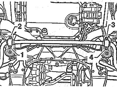
12.5. Unscrew nuts 1-4 of the anti-roll bar mounting brackets
6. First unscrew nut 3, then unscrew bolts 1 and 2 and remove the engine mount support (see illustration).
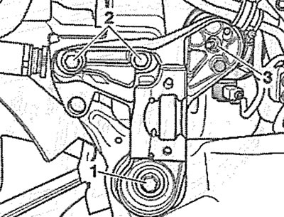
12.6. First unscrew nut 3, then unscrew bolts 1 and 2 and remove the engine mount support
7. Unscrew the bolt(see arrow in illustration) holder with which the oil line is attached to the bottom of the oil pan.
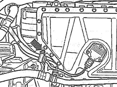
12.7. Unscrew the bolt (see arrow) the holder that secures the oil line to the bottom of the oil pan
8. Disconnect plug 1, unscrew the bolts (see arrows in the illustration) and remove the right engine mount support.
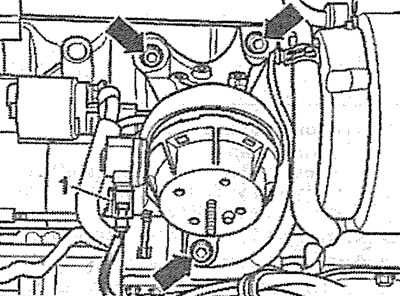
12.8. Disconnect plug 1, unscrew the bolts (see arrows) and remove the right engine mount support
9. Remove heat shield 1 and disconnect the right drive shaft end from the gearbox (see illustration).
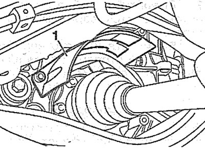
12.9. Remove heat shield 1 and disconnect the right drive shaft end from the gearbox
10. Unscrew nut 1 of the terminal of the ground (-) wire and disconnect the wire (see illustration).
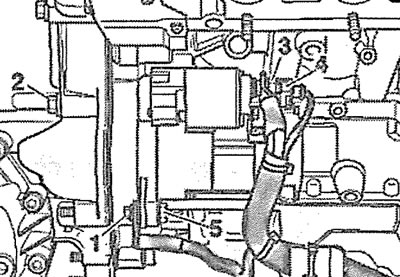
12.10. Unscrew nut 1 of the terminal of the ground (-) wire and disconnect the wire
11. Disconnect the plugs of wires 3 and 4 from the starter, unscrew bolts 2 and 5 and carefully remove the starter (see illustration 12.10).
Installation
The starter is installed in the reverse order of removal.
Information obtained from this resource: audimanual.ru