



Table of contents: Removal ↓ Installation ↓
Attention! When disconnecting the battery, the registered information is deleted from the memory of some electronic control units, for example, the codes of registered malfunctions in the engine, gearbox, ABS are deleted from the memory of the self-diagnostic system. Before disconnecting the battery, it is recommended to contact a specialized AUDI workshop to read the recorded codes. If these malfunctions appear later, they will be registered again by the self-diagnostic system.
The power window control unit will need to be activated after connecting the battery.
The serially installed radio receiver has an access code that prevents its use in case of theft of the radio receiver. The radio receiver is switched off and the code is deleted not only when the battery is disconnected, but also when the receiver itself is removed or when the fuse in the power supply circuit of the radio receiver burns out.
Before disconnecting the battery, the access code should be clarified and written down. Otherwise, the radio can only be put into operation with the help of a representative of the manufacturer or an AUDI workshop. It is also recommended to write down the radio settings for the radio stations.
When replacing the battery, purchase a new battery with ventilation. The gases released from the battery are removed through a special hose.
When installing a battery with a ventilation hole in the cell plugs, the plugs must be covered with a protective cover to prevent electrolyte from splashing onto engine compartment parts.
Caution! When performing work on the battery, take precautions, following the warning signs on the battery case.
Please read the following precautions when using the battery:
- a) The electrolyte has a corrosive effect, so use protective gloves and glasses. Do not place the battery on its side. In this case, the electrolyte may leak out through the ventilation hole;
- b) It is prohibited to use open fire and smoke near the battery. If the battery is disconnected without removing it from the tray in the engine compartment, it is recommended to cover or insulate its terminals as a precaution.
- c) wear protective glasses;
- d) Do not allow children to come into contact with the battery or electrolyte;
- d) used batteries must be disposed of.
Warning! When charging the battery, explosive gas is released.
Removal
1. Turn off the ignition.
2. Open and lift the hood.
3. Remove the rubber seal of the fairing grille in the direction indicated by the arrows in the illustration.
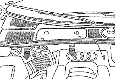
8.3. Remove the rubber seal of the fairing grille (see arrows)
4. Remove the grille 1 of the fairing by pushing it forward (see illustration 8.3).
5. Disconnect the ground (-) wire terminal from the negative battery terminal by unscrewing nut 1 (see illustration).
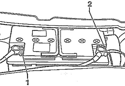
8.5. Disconnect the ground (-) wire terminal from the negative battery terminal by unscrewing nut 1
6. Remove the positive potential (+) wire terminal 2 from the positive pole (see illustration 8.5).
7. Disconnect the central battery ventilation hose (see arrow in illustration).
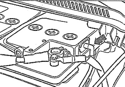
8.7. Disconnect the central battery ventilation hose (see arrow)
8. Unscrew bolt 3 of the clamp 2 securing the battery in the tray (see illustration).
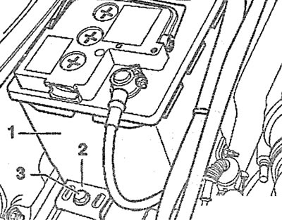
8.8. Unscrew bolt 3 of the clamp 2 securing the battery in the tray
9. Remove bracket 2 and take battery 1 out of the protective box (see illustration 8.8).
Installation
10. Clean the battery terminals with a brass brush.
11. Make sure that the ignition is off and all on-board electrical consumers are disconnected.
Caution! When installing the battery, make sure that the battery ventilation hose is not pinched. Otherwise, the gases generated during battery charging will not be discharged.
In the adapter through which the ventilation hose is connected to the battery (see arrow in illustration 8.7), there is a device that prevents the formation of sparks and thus prevents the ignition of flammable gases formed in the battery. For this reason, the battery should not be installed without a ventilation hose and, accordingly, without a protective device.
12. Install the battery so that the protrusion on the battery holder fits into the groove at the bottom of the battery case (see arrow in illustration).
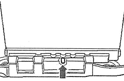
8.12. Install the battery so that the protrusion of the battery holder fits into the groove in the bottom of the battery case (see arrow)
13. Make sure that the hole on the bottom of the battery case is opposite the hole for the mounting bolt (see arrows in the illustration). In this case, the battery is fixed in the tray and will not move.
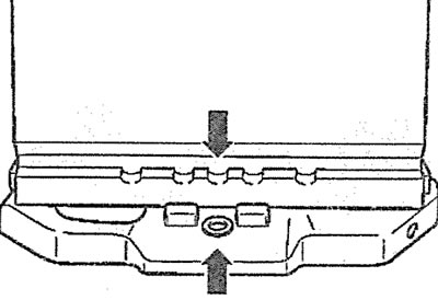
8.13. Make sure that the hole on the bottom of the battery case is opposite the hole for the mounting bolt (see arrows)
14. Make sure the battery is firmly seated in the tray and does not move even when you try to move it.
15. Install the clamp 2 and secure it with bolt 3, tightening it with a force of 22 Nm (see illustration 8.8).
Warning! If the battery is connected incorrectly, the generator and the electrical system as a whole may be damaged.
16. Connect the positive (+) potential wire terminal to the positive pole and tighten the nut to 7.5 Nm.
Attention! Do not lubricate the terminals, and do not try to put the terminal on the pole by applying force. This may cause damage to the battery case.
17. Connect the ground (-) cable terminal to the negative battery terminal (-) and tighten its clamp nut with a force of 7.5 Nm.
Attention! Before starting the engine for the first time after installing the battery, turn on the ignition for about 10 seconds. This will activate the engine control unit.