
Table of contents: Steering column module ↓ Steering column switches and control… ↓
1. The steering column module parts are shown in the illustration. The description of the removal/installation of the coil spring is given in Section 15.
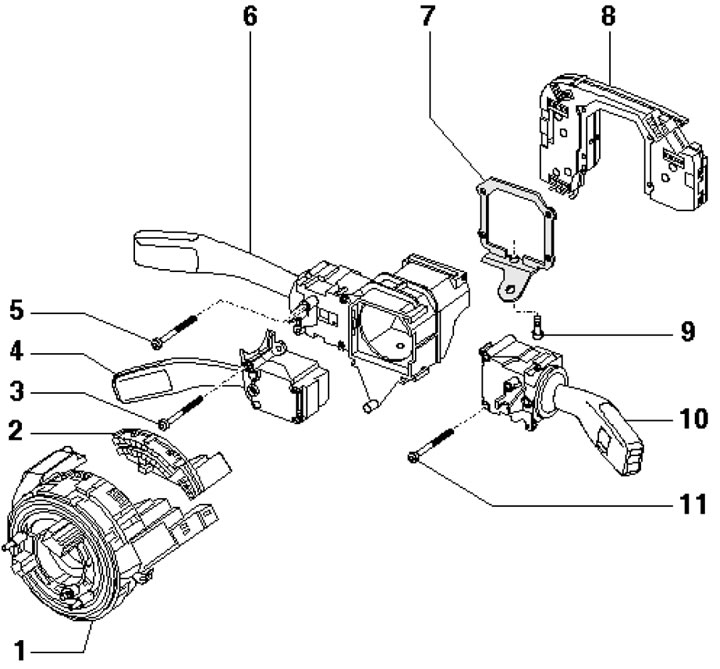
19.1 Steering Column Module Parts 1. Spiral spring; 2. Steering wheel angle sensor; 3, 5. Bolt; 4. Tempostat switch; 6. Left upper steering column switch; 7. Retainer; 8. Steering column electronics control unit; 9. Clamp bolt, 3 Nm; 10. Windscreen wiper control switch; 11. Bolt
Steering column module
2. Fully extend and lower the steering column.
3. Remove the steering wheel (see Chapter 10).
4. Remove the bolts (4-6 in the illustration), remove the cover (1) on the upper casing (2) of the steering column by separating it at points (A and B) using a small screwdriver. Remove the upper casing from the lower casing (3), remove the steering column locking lever (7) and remove the lower casing.
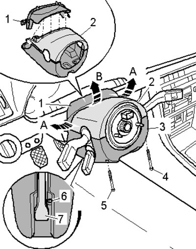
19.4. Removing the steering column covers
5. Unscrew the bolt (2 in the illustration), disconnect the connectors (1, 3 and 4).
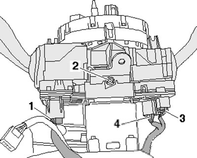
19.5. Steering column module fastening
Note: Discharge any static electricity before disconnecting the connector.
6. Press the lock (1 in the illustration) in the direction of the arrow to release the connector lock. Carefully remove the steering column paddles together with the steering column module.
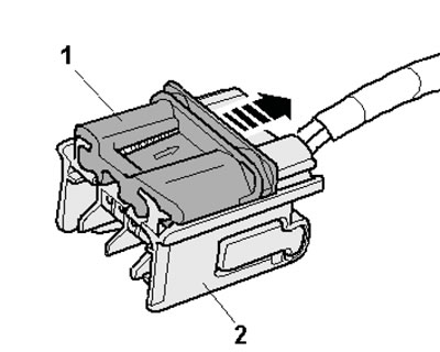
19.6. Disconnecting the connector
Steering column switches and control unit
7. Remove the steering column module (see subsection above).
8. Carefully press the clamps (arrows in illustration 15.6) and separate the coil spring with the steering wheel position sensor from the module.
9. Remove the bolts (arrows in the illustration), remove the steering column control unit (2) and the right steering column switch (3). Remove the cruise control switch (1), unscrew the bolt (5) and remove the retainer (4). Remove the upper left steering column switch.
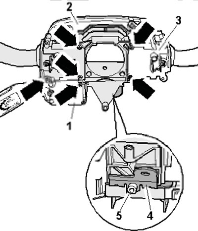
19.9. Removing the steering column switches