
Removal
1. Disconnect the negative cable from the battery, remove the gutter cover.
2. Remove the screw (arrow in illustration 5.23 Chapter 2) expansion tank mounts and move it to the side without disconnecting the hoses (1-3). Disconnect the K/L low coolant level sensor connector on the bottom of the expansion tank.
3. Press the brake pedal at least 60 mm and secure it with a suitable device (see illustration). Connect hoses to the bleed nipples of both left brake mechanisms, release the bleed nipples and let the brake fluid drain into a previously prepared container. This will release the pressure in the brake hydraulic drive. Tighten the bleed nipples.
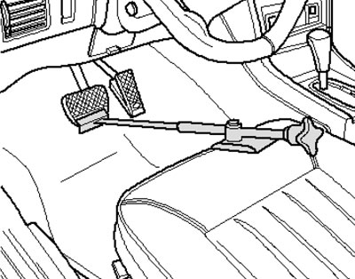
12.3. Fixing the brake pedal
4. Place a rag under the hydraulic modulator to collect any leaking brake fluid. Mark the brake pipes so as not to mix them up and disconnect them from the hydraulic modulator and the master brake cylinder (see illustration).
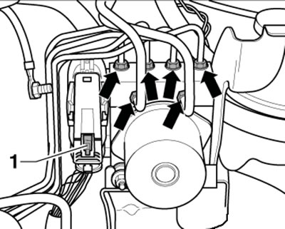
12.4. Brake pipes on the hydraulic modulator
5. Open the tube holder (see illustration) and press the red slider (1 in illustration 12.4) up.
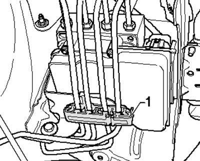
12.5. Brake pipe holder
6. Clean the connector with compressed air, pull the lock in the direction of the arrow (see illustration) and disconnect the connector.
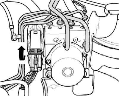
12.6. ABS/ESP control unit wiring connector
7. Remove the bolts (1 in the illustration) and remove the hydraulic modulator.
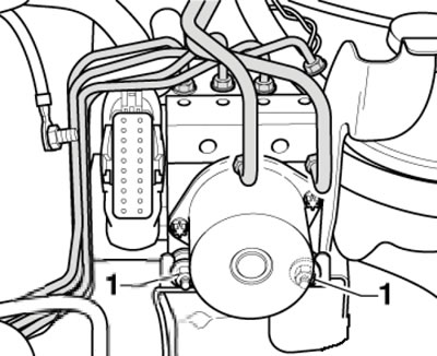
12.7. Hydraulic modulator assembly mounting bolts
8. Installation is performed in the reverse order of component dismantling. The hydraulic modulator fasteners should be finally tightened only after the brake pipe fastening nuts have been tightened.