
Table of contents: Petrol models ↓ Crankcase ventilation system ↓ Catalytic converter ↓ Exhaust gas recirculation system ↓ Fuel vapor recovery system ↓ Diesel models ↓ Controlled crankcase ventilation… ↓ Exhaust gas recirculation system ↓
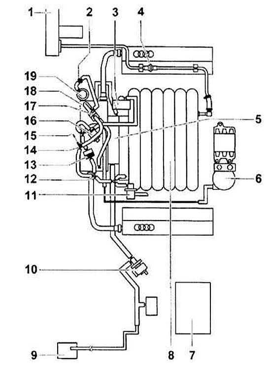
- 1 — EVAP system canister
- 2 - From the fuel tank
- 3 — EVAP Canister Purge Control Valve
- 4 — EVAP canister vacuum control valve
- 5 — Air cleaner housing
- 6 - Turbocharger
- 7 — Additional air intake control valve
- 8 — Fuel pressure regulator
- 9 — To the brake booster
- 10 - Vacuum control valve
- 11 - Vacuum booster
- 12 - To the leak detection pump
- 13 - Vacuum chamber
- 14 — Vacuum distributor "T"
- 15 - Vacuum control valve
- 16 — Additional air intake solenoid valve
- 17 — Crankcase ventilation
- 18 - Vacuum control valve
- 19 - To the leak detection pump
- 20 - Vacuum control valve
- 21 — Turbocharger cooler
- 22 — Throttle valve control module
- 23 — Turbocharger recirculation valve
- 24 — Air intake duct
- 25 — Additional air intake pump electric motor
- 26 — Power steering switch
- 27 — Throttle Valve Control Module
- 28 — EVAP Canister Purge Control Valve
- 29 — Compressed air pressure sensor
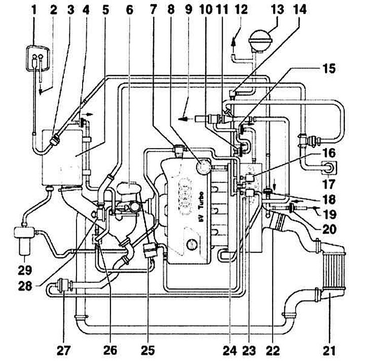
Vacuum Line Wiring Diagram. V6 Engine
- 1 - Brake booster
- 2 - Vacuum control valve
- 3 - Vacuum chamber (for inlet air duct switching valve)
- 4 - Vacuum control valve
- 5 — Throttle body
- 6 - Vacuum chamber
- 7 — Air cleaner housing
- 8 — Air intake duct
- 9 — EVAP system canister
- 10 — EVAP Canister Purge Control Valve
- 11 — Fuel pressure regulator
- 12 — Vacuum distributor "T" to EGR valve and K/V
- 13 - Vacuum control valve
- 14 — Vacuum distributor "T" to K/V
- 15 — K K/V
- 16 - Intake air duct switching valve
- 17 — EGR vacuum control solenoid valve
- 18 - Sound absorber
- 19 — EGR control valve
Petrol models
All petrol models must use unleaded petrol in their fuel systems. The engine management system is designed to provide maximum engine performance with minimum fuel consumption and emissions. The fuel vapor recovery system prevents fuel from escaping from the fuel tank into the atmosphere. An exhaust gas recirculation system is installed.
Crankcase ventilation system
To eliminate leaks of unburned hydrocarbons into the atmosphere, the engine is completely sealed. Gases and oil vapors formed in the crankcase enter the intake manifold through a mesh filter and burn in the cylinders together with the fuel.
Gases are removed from the crankcase due to the difference in pressure in the crankcase and the intake manifold (crankcase pressure is higher).
Catalytic converter
To reduce the amount of harmful emissions into the atmosphere, a three-function catalytic converter is built into the exhaust system on all petrol models. The fuel injection control system has a feedback loop, which includes a lambda probe. This sensor, installed in the exhaust system, constantly informs the control unit about the composition of the exhaust gases. Depending on the data received, the control unit adjusts the quality of the mixture supplied to the combustion chambers and, thus, optimizes fuel combustion.
The lambda probe has a built-in heating element, which is switched on by the control unit via a special relay. The working surface of the lambda probe is sensitive to changes in the oxygen content in the gases. Depending on the oxygen concentration, the sensor sends signals of different voltages. If the mixture is over-enriched - the oxygen content in the exhaust gases is very low, the sensor sends signals with low voltage. The voltage increases as the mixture becomes leaner and the oxygen content in the gases increases. The converter works most effectively with optimal quality of the combustible mixture (14.7 parts air to 1 part fuel). At the optimum oxygen concentration in the exhaust gases, a jump in voltage occurs on the sensor. This jump is the starting point for the control unit when adjusting the mixture quality.
Two sensors are installed. One is before and the other is after the converter. This allows for more accurate monitoring of the exhaust gas composition.
Exhaust gas recirculation system
The exhaust gas recirculation system reduces the amount of NOx in the exhaust gases. To do this, a small portion of the exhaust gases is fed into the intake manifold through a special valve. The recirculation system valve is controlled by the control unit.
Fuel vapor recovery system
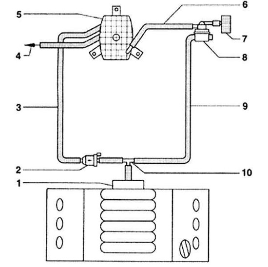
Fuel Evaporative Emission System Lines 1.8L Engine
- 1 - Vacuum control valve
- 2 — EVAP Canister Purge Control Valve
- 3 - Outlet pipe from EVAP canister purge control valve
- 4 - Outlet pipe from gravity valve
- 5 — EVAP system canister
- 6 - To the leak detection pump
- 7 — Air filter housing
- 8 - Leak detection pump
- 9 - Vacuum hose from air intake manifold to leak detection pump
- 10 - Vacuum chamber
- 11 — Check valve
- 12 — Vacuum distributor "T"
- 13 — Throttle valve control module
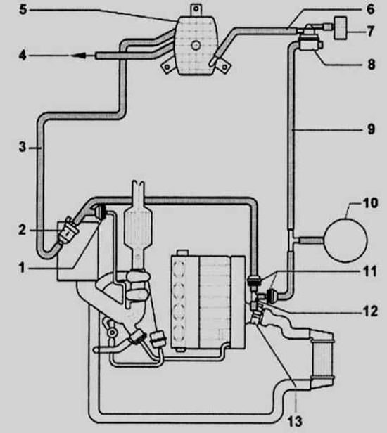
Fuel Evaporative Emission System Lines V6 Engine
- 1 - Throttle actuator control module
- 2 — EVAP Canister Purge Control Valve
- 3 - Outlet pipe from EVAP canister purge control valve
- 4 - Outlet pipe from gravity valve
- 5 — EVAP system canister
- 6 - Vacuum hose from air intake manifold to leak detection pump
- 7 — Air filter housing
- 8 - Leak detection pump
- 9 — Intake air duct vacuum hose to throttle actuator control module
- 10 - Vacuum connection "T"
To reduce the emission of unburned hydrocarbons into the atmosphere, all petrol models are equipped with a fuel recovery system. The fuel filler neck of the fuel tank is hermetically sealed with a lid, and a carbon adsorber is installed under the fuel tank. It collects fuel vapors that form in the tank when the car is parked and stores them there until the control unit signals the adsorber to purge. Then the fuel vapors begin to flow through the purge valve into the intake manifold, where they mix with the working mixture and then burn in the usual way in the combustion chambers.
To ensure normal engine operation at idle speed and during warm-up, the control unit keeps the valve closed. This prevents unburned fuel from entering the converter (at high idle speed the mixture is too rich). After the engine warms up, the valve begins to open and close, supplying fuel vapors into the intake tract.
Diesel models
The engine management system operates in such a way as to obtain maximum output from the engine with minimum fuel consumption and toxicity of exhaust gases. To further reduce toxicity of gases, several additional systems are installed on the car. The crankcase ventilation system reduces gas leaks into the atmosphere from the engine lubrication system. The catalytic converter reduces toxicity of exhaust gases. An exhaust gas recirculation system is installed.
Controlled crankcase ventilation system
To eliminate leaks of unburned hydrocarbons into the atmosphere, the engine is completely sealed. Gases and oil vapors formed in the crankcase enter the intake manifold through a mesh filter and burn in the cylinders together with the fuel.
Gases are removed from the crankcase due to the difference in pressure in the crankcase and the intake manifold (crankcase pressure is higher). All diesel models are equipped with a ventilation valve. It is located on the cylinder head cover and controls the flow of gases from the crankcase.
Exhaust gas recirculation system
All diesel models are also equipped with an exhaust gas recirculation system. This system reduces the amount of NOx in the exhaust gases. To do this, a small portion of the exhaust gases is fed into the intake manifold through a special valve. The recirculation valve is controlled by the control unit.
(The original source of the article can be found on the website: AudiManual)