
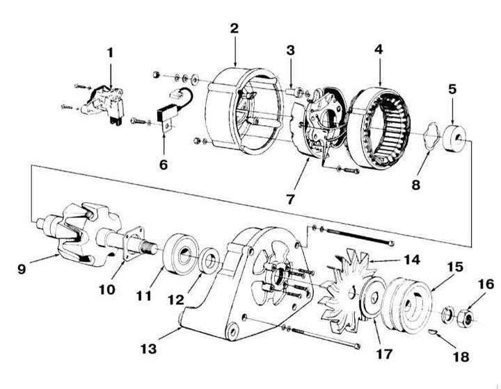
- 1 - Voltage regulator
- 2 - Rear casing
- 3 - Isolator
- 4 — Stator
- 5 - Front bearing
- 6 - Capacitor
- 7 - Diode assembly
- 8 — Wave bearing washer
- 9 — Rotor
- 10 — Bearing tensioner
- 11 — Rear bearing
- 12 — Seal
- 13 — Front casing
- 14 — Impeller
- 15 — Pulley
- 16 - Nut
- 17 — Spacer
- 18 — Key
The vehicle is equipped with an alternator. When installing additional electrical equipment, make sure that the alternator has sufficient power to power this equipment.
The generator is driven by a ribbed belt from the engine crankshaft.
The generator is a three-phase synchronous electric machine with electromagnetic excitation. To convert alternating current into direct current, a diode rectifier is built into the generator. The voltage is regulated by a built-in microelectronic voltage regulator.
When the generator is operating, the electric current flowing through the excitation winding creates a magnetic flux around the rotor poles. When the rotor rotates, the south and north poles of the rotor pass under each stator tooth, and the working magnetic flux passing through the stator teeth changes in magnitude and voltage. This variable magnetic flux creates an electromotive force in the stator winding. The wedge-shaped rotor pole pieces are selected in such a way that it allows obtaining a nearly sinusoidal shape of the electromotive force curve.
At high generator rotor speed, when the generator voltage becomes higher than 13.6 – 14.6 V, the voltage regulator locks and the current does not pass through the excitation winding. The generator voltage drops, the regulator unlocks and again passes the current through the excitation winding. The higher the generator rotor speed, the longer the regulator locks, and therefore the more the generator output voltage decreases. The process of locking and unlocking the regulator occurs with a high frequency, so the voltage fluctuations at the generator output are not noticeable, and it can practically be considered constant, maintained at a level of 13.6–14.6 V.
The charging system does not require periodic maintenance, however the drive belt, battery and cables with connectors should be maintained in accordance with the instructions given in Chapter Routine care and maintenance intervals.
When the ignition is turned on, a control lamp should light up on the dashboard, signaling a discharged battery. It should go out immediately after the engine starts. If it does not go out or lights up while driving, the charging system is faulty. If the lamp does not light up when the ignition is turned on, then either the lamp itself has burned out, its wiring is broken, or the generator is faulty.
Safety precautions when working with a generator
1. Never disconnect the battery or voltage regulator while the engine and generator are running.
2. Never short-circuit the generator excitation terminal or the cable attached to it to ground.
3. Never mix up the voltage regulator wires.
4. Never turn on the voltage regulator if it is connected to ground (instant damage).
5. Never remove the generator unless the battery is disconnected from the circuit.
6. When installing the battery, make sure that the negative terminal is connected to ground.
7. Never use a voltage indicator that is connected directly to the household network (110 or 220 V). Use only 12V indicator.
8. Do not test diodes by applying voltage greater than 12 V or with a megohmmeter, as it has too high a voltage for diodes and they will be broken during testing (a short circuit will occur). When checking the insulation of electrical wiring with a megohmmeter, it is necessary to disconnect all wires from the generator.
9. If the battery is charged in the installed state by the charger, both battery cables should be disconnected. Connect the positive terminal of the charger to the positive terminal of the battery, and the negative terminal of the charger to the negative terminal of the battery.
10. Disconnect all wires from the generator and battery when electric welding any body parts.
11. Check the circuits and components of electrical equipment and troubleshoot with the engine not running and the battery disconnected.
12. Incorrect connection of wires leads to destruction of the rectifier and voltage regulator.
(Read the original source on the website AUDIMANUAL.RU)