
Instructions, Reinstall all cable ties removed or cut during dismantling. Observe repair instructions, especially regarding contact corrosion.
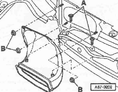
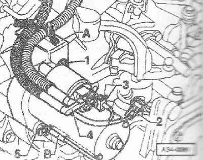
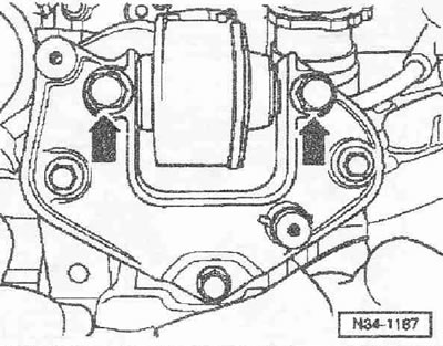
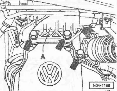
Disconnect the ground wire from the battery terminal (in the trunk) with the ignition off. Install the hood as follows: Unlock the service cover from the inside. Unlock the hood cover "arrows" and pull it forward a little. Remove the hood cover and place it with the side covered with a protective cover down. Remove the rubber seal on the water drainage box. Remove the windshield wiper arm and fairing. Remove both bolts "A" and three hex nuts "B". Remove the fresh air intake duct forward.
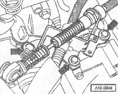
Remove the engine casing by unscrewing the bolts. Remove the cable counter support from the gearbox "arrows".
Unscrew nut "1" and bolt "2" and remove cross support "A".
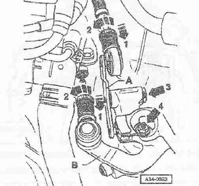
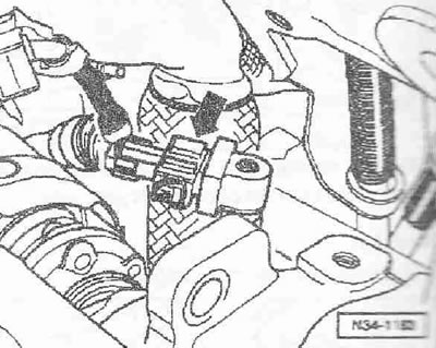
Pull the safety mechanism on the switching cable and on the selection cable forward until it stops "arrow 1" and then lock it by moving left "arrow 2". Remove the locking washer "arrow 3" and remove the intermediate gear selector lever "A". Remove the gearbox selector "B", then unscrew the nut "arrow 4". Then fix the shift cable and gear selection cable at the top.
Unscrew the working cylinder of the "arrow", remove the tubular-hose line from the bracket on the gearbox and put it aside, secure it with wire, do not open the system of lines.
Instructions: Press the clutch pedal.
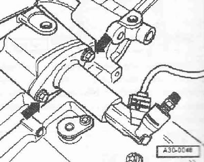
Disconnect the plug connector from the speedometer sensor "G22" ("arrow"). Unscrew the connecting screws of the gearbox/engine at the top.
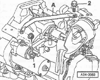
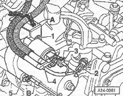
Remove bracket "A" from the starter. Then remove the upper mounting bolt on the starter "1". Disconnect the plug connector of the reverse light switch "F4" ("2"). Disconnect plug connector "3" from the starter. Unscrew wire "4" of the electromagnetic switch terminal 30.
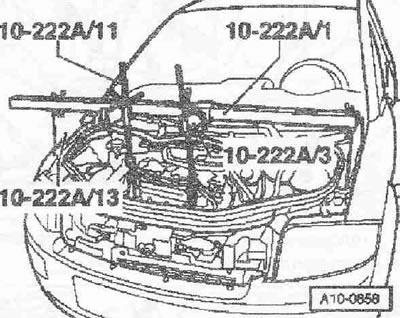
Install the crossmember "10. 222 A" with the adapter "10. 222 A /13" on the connecting edge of the wing. Slightly tighten the engine with the gearbox using the lead screws. Loosen the wheel bolts of the left front wheel. Raise the car. Remove the left wheel. Remove the noise insulation screen.
Unscrew the ground wire "B" from the lower starter mounting bolt. Unscrew the starter mounting bolt "5" and remove the starter.
Remove the heat shield of the "arrow" of the drive shaft. Disconnect the drive shafts from the shafts with the gearbox flange. Raise and secure the right drive shaft, avoiding damage to the protective surface coating.
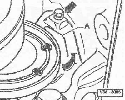
Remove the small shield "A" for the flywheel behind the right shaft with the "arrow" flange.
Remove the pendulum support "arrow".
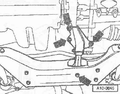
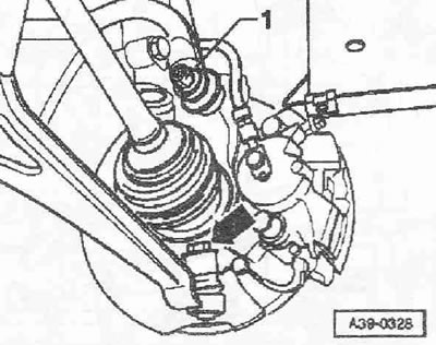
Disconnect the left stabilizer strut "1". Disconnect the left suspension arm from the hub bearing housing "arrow". Remove the mudguard on the left wheel arch. Turn the steering knuckle outward. Remove the left drive shaft through the opening between the subframe and the gearbox. At the same time, insert the drive shaft into the wheel arch and secure it, for example, with wire on the shock absorber strut.
Unscrew the hexagonal head bolts "arrows" of the left support of the power unit from the support of the gearbox. Give the power unit an inclined position, for this purpose lower the crossmember "10.222 A" using the lead screws.
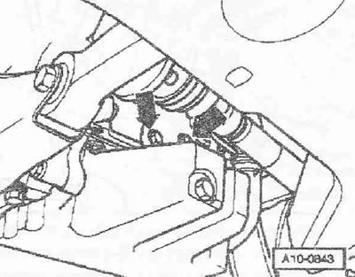
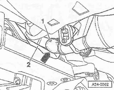
Lower the power unit so that the exhaust pipe "1" is adjacent to the heat shield "2" above the subframe "arrow". It is prohibited to bend the detachable element of the exhaust system at an angle greater than 10° - risk of damage.
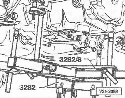
Remove the gearbox console "A" "arrows". The bolts for fastening the "arrow" of the gearbox console "A" must be accessible. Equip the gearbox lift with the gearbox grip "3282" with the adjustment template "3282/8" for the gearbox "02A" and fasteners as described below: install the adjustment template "3282/8" on the gearbox grip "3282". (The adjustment template "3282/8" has only one mounting position). Orient the gearbox support brackets in accordance with the holes in the adjustment plate "3282/8".
Screw on fasteners "A" as shown on the adjustment plate "3282/8".
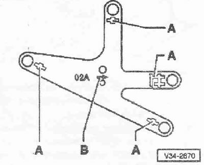
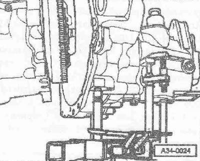
Install the gearbox lift under the vehicle, arrow "B" on the adjustment template "3282/8" points in the direction of vehicle travel. Align the installation template "3282/8" parallel to the gearbox and secure the locking support to it. Unscrew the lower connecting screws of the gearbox to the engine.
Press the gearbox away from the fitted bushings and carefully tilt it toward the subframe. Turn the gearbox slightly downwards in the differential area.
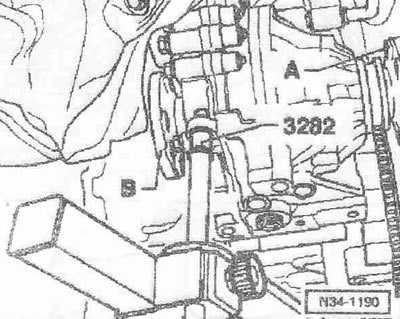
After this, carefully lower the gearbox, while moving it with the right shaft with flange "A", as shown, in the flywheel area and the left shaft with flange "B" in the subframe area. Change the position of the gearbox when lowering with the lead screws for the "3282" gearbox.
(The original source of the article can be found on the website: «AudiManual.ru»)