
Table of contents: Removal ↓ Installation ↓
Removal
Remove the engine hood. Remove the poly V-belt.
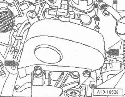
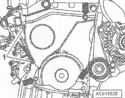
Remove the upper cover of the toothed belt, to do this, open the clamping clamps "arrows". Set the crankshaft in the direction of engine rotation to "TDC". The risk on the pulley of the poly V-belt for the crankshaft should coincide with the edge of the mark "0".
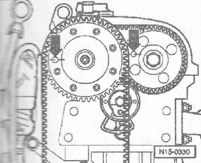
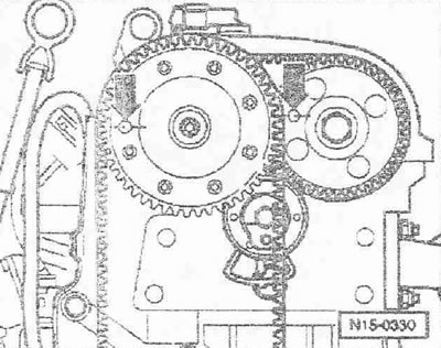
The fixing holes in the intake camshaft gear with the valve timing adjuster and in the exhaust camshaft gear must be aligned with the gauge holes in the camshaft bearing housing "arrows".
Instructions: If the fixing holes are on opposite sides, the crankshaft must be turned one more revolution.
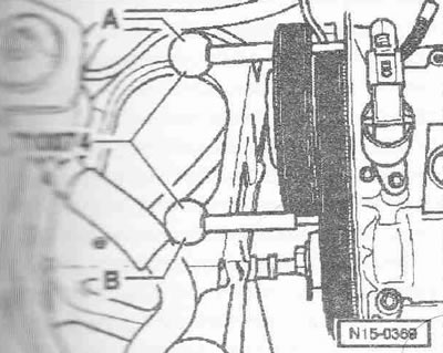
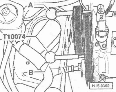
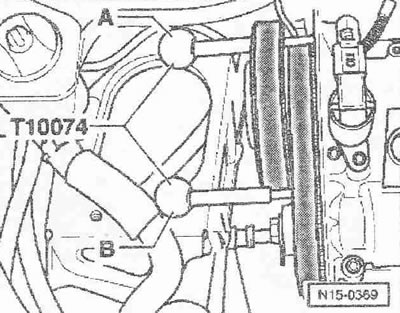
Lock the camshafts using the locking pins "T10074": the locking pin "A" must be inserted through the locking hole of the intake camshaft gear into the calibration hole on the camshaft bearing housing. The locking pin "B" must be inserted through the locking hole of the exhaust camshaft gear into the calibration hole on the camshaft bearing housing. Remove the engine mount.
Remove the pulley of the poly V-belt for the crankshaft. Remove the lower cover for the toothed belt, for this unscrew the bolts "arrows".
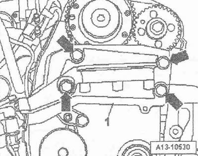
Unscrew the bolts "arrows" and remove the engine support bracket "1".
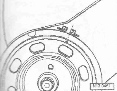
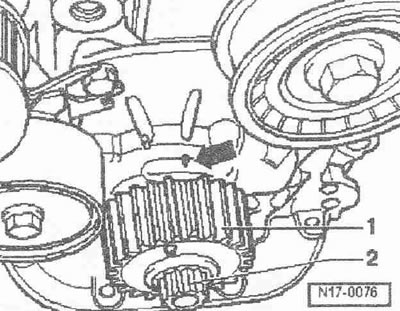
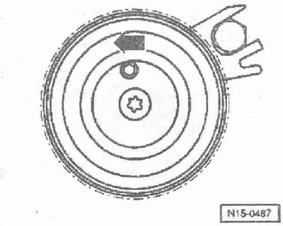
Check the "TDC" position of the camshaft: the flattened tooth on the toothed belt pinion "1" for the crankshaft must coincide with the "arrow" mark on the oil pump housing. Do not take pos. "2" into account.
Caution! Risk of damage to the previously used poly V-belt when changing its running direction. For reinstallation, mark the running direction of the poly V-belt with chalk or a felt-tip pen before removing it.
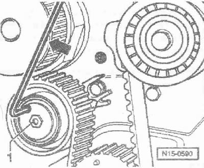
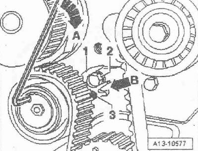
Unscrew bolt "1" for the main drive belt tension roller. Turn the tension roller counterclockwise "arrow" with a socket Allen key and remove the toothed belt.
Installation
Installation is in the reverse order, taking into account the following: the intake camshaft gear with the valve timing adjuster and the exhaust camshaft are secured with locking pins "T10074".
If removed, install the timing belt tension roller for the main drive and turn it counterclockwise with an Allen key to the indicated "arrow" position.
Tighten the bolt for the main drive toothed belt tensioner roller by hand. Bolt "2" for the oil pump housing should be in the recess of the support plate.
Instructions. Ignore position "3" and "arrows". Observe the direction of travel of the previously used belt.
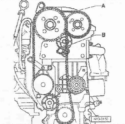
Install the toothed belt for the main drive "B" in the sequence, coolant pump, tension roller, crankshaft and intake camshaft.
A. Toothed belt for coupled drive.
Tighten the toothed belt by turning the tension roller clockwise "arrow A" until the pointer "3" is above the mark "arrow B" in the main plate "1". Tighten the bolt for the toothed belt tension roller for the main drive. Remove the locking pin "T10074". Turn the crankshaft in the direction of engine rotation by 2 turns and set it again to "TDC".
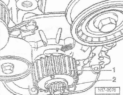
Check the "TDC" position of the camshaft: the flattened tooth on the toothed belt gear "1" for the crankshaft must coincide with the "arrow" mark on the oil pump housing. Ignore pos. "2". The locking holes in the inlet camshaft gear with the valve timing adjuster and in the exhaust camshaft gear must be coaxial with the calibrated holes in the camshaft bearing housing "arrows".
Lock the camshafts using the locking pins "T10074": Locking pin "A" must be inserted through the locking hole of the intake camshaft gear into the calibration hole on the camshaft bearing housing. Locking pin "3" must be inserted through the locking hole of the exhaust camshaft gear into the calibration hole on the camshaft bearing housing.
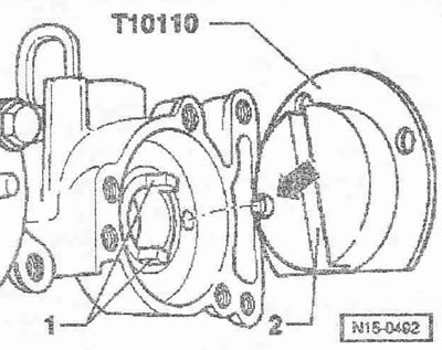
Install the "T10110" locking flange on the gearbox side of the camshaft bearing housing for the intake camshaft as follows: the "arrow" pin of the "T10110" locking flange must enter the small hole of the intake camshaft thrust bearing. The "1" journals of the intake camshaft must enter the "2" recess of the "T10110" locking flange.
Turn the intake camshaft until it stops against the direction of engine rotation using the hexagon of the "T10110" locking flange and hold it there.
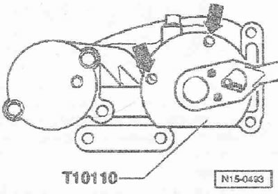
When the valve timing is set correctly, the "arrow" holes in the "T10110" fixing flange should be aligned with the threaded holes in the camshaft bearing housing. If the holes are not aligned, repeat the adjustment.
Installation is in the reverse order, in this case it is necessary to install the support bracket and engine supports, install the poly V-belt pulley for the crankshaft.