
Table of contents: Removal/Installing a V6 Engine… ↓ Disconnecting and connecting… ↓ Removal and installation a V8 engine… ↓
Removal/Installing a V6 Engine Compressor
Comment:
- The compressor can be separated from the holder without disconnecting the refrigerant lines.
- Contrary to the description below, the compressor can be removed upwards if the refrigerant lines are first disconnected from it and the power steering pump is removed.
1. Remove the sound insulation panels under the engine compartment (see Section 19 of Chapter 1).
2. Remove the front left wheel arch liner and air hose (see illustration 4.16 Chapter 2).
3. Remove the drive belt (see Chapter 2).
4. If present, disconnect the G454 sensor connector (2 in illustration 4.19 Chapter 2) coolant temperature. If the compressor needs to be removed, bleed the refrigerant from the refrigeration unit, disconnect the refrigerant lines from the compressor and plug any open holes. Remove the holders (1 and 5) and separate the coolant hose from the support on the side member.
5. Mark the connector of the N280 regulating valve (1 in the illustration), to avoid confusion with the engine mount connector.
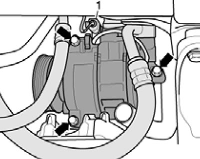
17.5. Compressor connector and bolts.
Unscrew the three bolts (arrows) and remove the compressor towards the left wheel arch.
6. Holder (D in the illustration) the compressor remains on the engine.
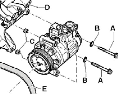
17.6. Compressor mounting parts.
Clean the mating surfaces, install them in the sleeve holder (C) and tighten the bolts (A) with washers to 25 Nm.
7. Installation is carried out in reverse order. Refrigerant lines must be located in appropriate holders (if available).
Disconnecting and connecting refrigerant lines
8. Drain the refrigerant from the refrigeration unit.
9. If present, disconnect the connector of the coolant temperature sensor G454.
10. Remove the bolts (And in the illustration) and disconnect the lines (B and C) from the compressor.
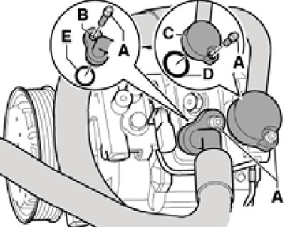
17.10. Refrigerant line connections on the compressor.
Replace the O-rings (D and E).
11. Connect the refrigerant lines in reverse order. Tighten the bolts to 20 Nm.
Removal and installation a V8 engine compressor
12. Drain the refrigerant from the refrigeration unit.
13. Remove the top engine cover (see Section 19 of Chapter 1) and drive belt (see Chapter 2).
14. Unscrew the bolt (1 in illustration 35.17 Chapter 2) refrigerant line holder.
15. Remove the N345 valve connectors from the holder and disconnect them (1 in the illustration) switching of the EGR cooler and the compressor control valve N280 (2).
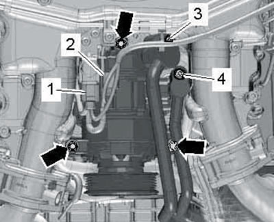
17.15. Compressor connections and bolts.
Remove bolts (3 and 4) and disconnect refrigerant lines. Seal any open holes. Remove the bolts (arrows) and remove the compressor.
16. Make sure the bushings are present (And in the illustration).
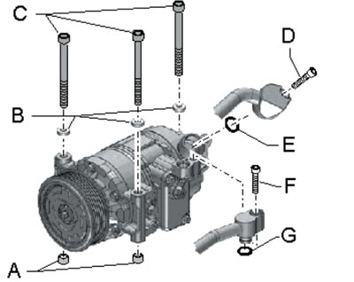
17.16. Compressor mounting parts.
Install the compressor and tighten the bolts (C) with washers (B) to 25 Nm. Connect the refrigerant lines with new sealing rings (E and G) and tighten the bolts (D and F) to 20 Nm.
17. Further installation is carried out in reverse order.