
Table of contents: Front body ↓ Rear body ↓
Front body
Note: When removing, pay attention to the length of the bolts so that they can be screwed back into place when installing. An assistant will be required for installation.
1. Move the front seats as far back as possible and turn off the ignition.
2. Drain the refrigerant from the refrigeration unit.
3. Disconnect the negative battery cable (see Chapter 5).
4. Open the expansion tank to relieve coolant pressure.
5. Remove the ECM (see Chapter 5) and its holder to gain access to the nuts (1 in the illustration). Remove these nuts and remove the air intake grille (A).
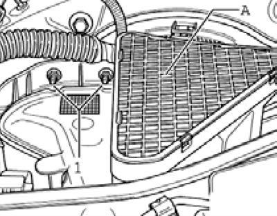
14.5. Nuts (1) and air intake grille (A).
6. Reach into the air intake from above and release the clips (1 in the illustration).
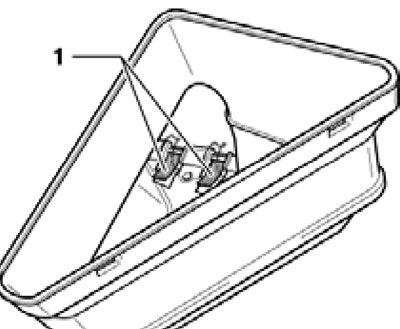
14.6. Air intake clamps.
Remove the air intake.
7. Follow the steps described in paragraphs 3-5 of Section 12.
8. Remove the bolts (And in the illustration) and disconnect the refrigerant lines (B and C) from the expansion valve.
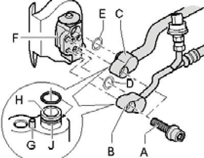
14.8. Fastening the refrigerant lines to the front expansion valve.
Cap any open refrigerant lines and expansion valve ports to prevent dirt from entering the circuit.
9. Remove the bolts (1 in the illustration) and remove the front expansion valve.
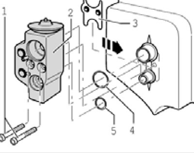
14.9. Fastening the front expansion valve.
10. Seal the open ports of the expansion valve and install the caps on the evaporator (A and B in the illustration), to prevent dirt from entering the refrigerant circuit.
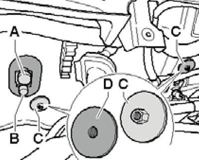
14.10. Caps (A and B) on the evaporator and nut (C) with rubber layer (D).
11. Follow the steps described in paragraphs 6-7 of Section 12.
12. Remove the air ducts (A and B in the illustration), leading to the front footwells.
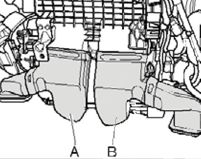
14.12. Air ducts to the front footwells.
13. Mark the installation position of the nut flange with a waterproof marker (From the illustration 14.10) relative to the bulkhead. Remove the two nuts (C) and make sure the caps (A and B) are present.
Note: There is a rubber layer on the back side of the nut flange for sealing purposes.
14. Disconnect the connector (And in the illustration) and release the wiring holder (B) and other holders from the climate control system housing (D) (for example, coupler C).
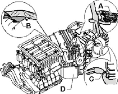
14.14. Connector (A) and holders (B and C) on the climate control system housing (D).
On models with the "Z35" additional heating element, disconnect the corresponding electrical wiring. Remove the climate control system housing towards the starboard side.
15. Check the location of the glued rubber elements (And in the illustration); if necessary, glue them to the supports (F).
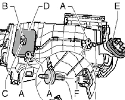
14.15. Controlled parts on the climate control system housing.
Make sure the caps (B and C) are on the evaporator. Check the foam seal (D) for proper position and integrity. Check the connection (E) on the coolant pipe flange for proper integrity and position. Check all other seals in the climate control system housing.
16. Further installation is carried out in the reverse order of removal. When tightening the nuts (From the illustration 14.10) align the marks made during removal of the climate control system housings. When connecting the coolant hoses to the heater radiator, follow the information provided in Section 12. Use new expansion valve and refrigerant line O-rings. Tighten the expansion valve and refrigerant lines to 10 Nm.
Rear body
17. Drain the refrigerant from the refrigeration unit.
18. Turn off the ignition.
19. Open the expansion tank to relieve coolant pressure.
20. Disconnect the refrigerant lines from the rear expansion valve (see illustration 13.3).
21. Install the rear housing of the climate control system to the service position (see Section 11).
22. Mark the coolant hoses (A and B in illustration 12.35), so as not to confuse them. Clamp the coolant hoses, take measures to collect the leaking coolant and disconnect the coolant hoses from the rear radiator (C).
23. Remove the rear housing of the climate control system, holding it so that the coolant does not spill out of the radiator.
24. Installation is carried out in reverse order. When connecting the coolant hoses to the heater radiator, follow the information provided in Section 12. Use new expansion valve and refrigerant line O-rings. Tighten the expansion valve and refrigerant lines to 10 Nm.
[The article is a reprint of material from AudiManual.ru]