



Table of contents: Installation ↓ Assignment of contacts in the… ↓ Connection layout on the fuel gauge… ↓ Layout of contacts of 5-pin… ↓ Purpose of contacts of the connector… ↓ Layout of the 2-pin plug connector… ↓ Purpose of contacts of coolant level… ↓ Layout of the 2-pin plug connector… ↓ Distribution of electrical charges… ↓ Removal the outside temperature… ↓ Installation ↓ Removal the radio clock receiver… ↓ Installation ↓
Note: Do not disassemble the instrument cluster control unit. It is not necessary to remove the steering wheel to remove the instrument cluster.
If the instrument cluster is being replaced with a used instrument cluster "J285", then select the "Replace" function of the corresponding used one in the "Guided fault finding" or "Guided functions" operating mode.
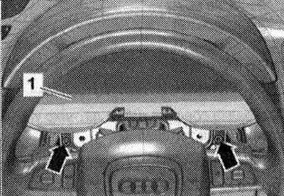
Select function or path: car brand -engine letter designation -17 instrument cluster J285 -17 replacement used (rem. gr. 90). Follow the further instructions on the display of the diagnostic tester. Set the steering wheel as far back and down as possible, use the full range of adjustment of the steering column position for this. Switch off the ignition. Remove the joint cover. Remove the joint cover from the upper part of the steering column. Unscrew the bolts "arrows". Move the instrument cluster "1" so that it adjoins the steering wheel. Disconnect the electrical plug connection.
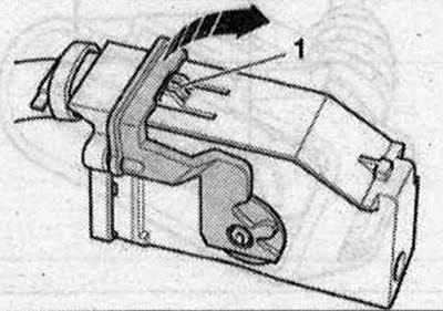
To disconnect the electrical plug connection, press the lock "1", turn the locking bracket in the "direction of the arrow" and disconnect the plug connection.
Remove the instrument cluster located between the steering wheel and the control panel towards the driver's side.
Installation
Installation in reverse order: follow further instructions on the display of the diagnostic tester with the new instrument cluster.
Assignment of contacts in the multi-pin plug connector in the instrument panel
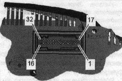
32-pin connector, gray 1. not busy; 2. CAN bus wake-up wire, screen; 3. CAN Bus Wake-up Wire, Low; 4. CAN bus wake-up wire, High; 5. Ground wire of the fuel level sensor "G". Contact 2; 6. Fuel level sensor "G". Contact 4; 7. Fuel level sensor "G". Contact 3; 8-22 not busy; 23. Radio clock 5V; 24. Radio clock signal; 25-28. not busy; 29. Terminal 31; 30. Terminal 31; 31. Terminal 30; 32. Terminal 30.
Connection layout on the fuel gauge sensor "G"
Disconnect the 5-pin electrical connector from the blind flange of the fuel tank.
Layout of contacts of 5-pin connector of fuel level sensor "G"
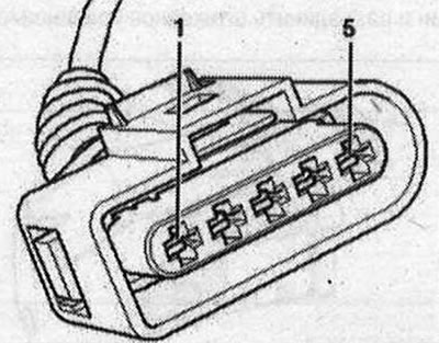
1. Positive terminal of fuel pre-supply pump "G6"; 2. Cable from fuel level indicator sensor "G" to instrument cluster (sensor ground cable) - contact 5; 3. Cable from fuel level indicator sensor "G" to instrument cluster (fuel tank level indication) - contact 7; 4. Cable from fuel gauge sensor "G" to instrument cluster (fuel tank level indication) - contact 6; 5. "Ground" of the fuel pre-supply pump "G6".
Purpose of contacts of the connector of the coolant temperature sensor "G62". FSI and TFSI engines
Disconnect the 2-pin electrical connector from the coolant temperature sensor "G62". The sensor cannot be removed.
Layout of the 2-pin plug connector on the coolant temperature sensor G62-
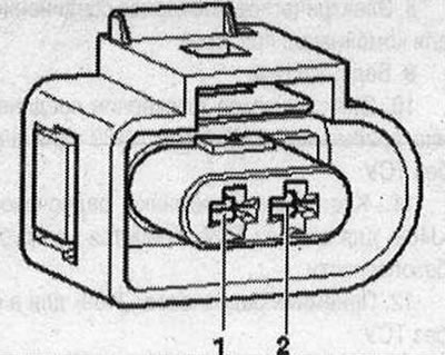
1. Sensor mass; 2. Cable connection from the coolant temperature sensor "G62" to the engine control unit
Purpose of contacts of coolant level sensor connectors "G62" / "G83". TDI engines
Disconnect the 2-pin electrical connector from the coolant temperature sensor "G62". The sensor cannot be removed. Disconnect the 2-pin electrical connector from the coolant temperature sensor at the radiator outlet "G83". The sensor cannot be removed.
Layout of the 2-pin plug connector on the coolant temperature sensor "G62"
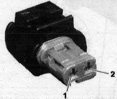
- 1. Sensor mass
- 2. Cable connection from the coolant temperature sensor "G62" to the engine control unit
Distribution of electrical charges of the 2-pin connector of the coolant temperature sensor at the outlet of the cooling system "G83"
- 1. Sensor mass
- 2. Cable connection from the coolant temperature sensor at the outlet of the cooling system "G83" to the engine control unit
Removal the outside temperature sensor "G17"
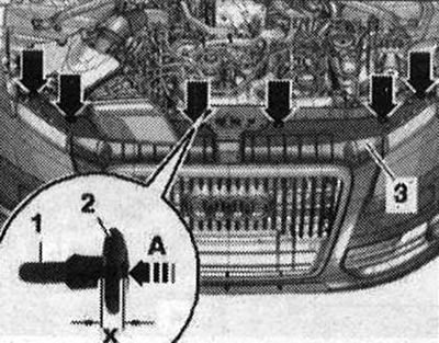
Switch off ignition. To remove the spacer clips "arrows", carefully insert pin "1" at a distance "x" into the clip until you hear "arrow A" locking. Size "x" = 5 mm. Remove the unlocked clip "2" with the pin. Lift cover "3" on the radiator frame and hang it on the radiator grille.
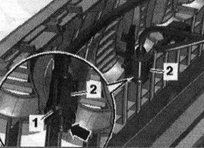
Disconnect the electrical plug connection "2". Carefully squeeze the clamps "arrow" and pull the outside temperature sensor "G17" "pos. 1" upwards from the mount.
Installation
Installation in reverse order: install the radiator frame trim on the radiator grille.
Removal the radio clock receiver "J489"
Turn off the ignition. Remove the rear bumper trim.
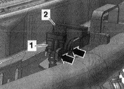
Cars without towing hitch: Lift the "arrow" clips and remove the "489" radio clock receiver "pos. 3" from the mount "1" upwards. Disconnect the connector "2" on the "J489" radio clock receiver.
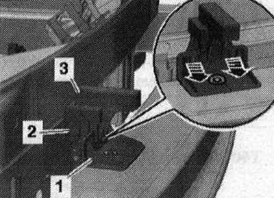
Cars with towing hitch: Unscrew the "arrow" bolts and remove the receiver for the radio clock "J489" no. 3. 2-. Disconnect connector "1" on the receiver for the radio clock "J489".
Installation
Installation in reverse order: Install the rear bumper trim. If the bumper trim on a vehicle with lane change assist has been removed, the lane change assist control unit "J769" / "J770" must be recalibrated.
The original publication in its entirety is posted on the website AudiManual.ru