
Repair Chevrolet Repair Toyota Repair Honda Repair AvtoVAZ Repair Mercedes-Benz Repair BMW Repair Opel
Home  |  Contacts  |  Sitemap  |    
English Русский
Български
Беларускі
Український
Српски
Hrvatski
Română
Polski
Slovenský
Magyar
AudiManual.ru


  • AUDI 80
  • AUDI 100
  • AUDI A3
  • AUDI A4
  • AUDI A6
  • AUDI A8
  • AUDI Q
  • OTHER
  • ARTICLES
B8 (2007-2015) B7 (2004-2008) B6 (2000-2006) B6 (2000-2006, petrol) B5 (1994-2001) B5 (1994-2001, petrol)

Fuel tank with attachments, all-wheel drive (Audi A4 B8)

  • Home
  • Audi A4
  • B8 (2007-2015)
  • Power unit
  • Fuel system (petrol)
  • Fuel tank with attachments, all-wheel drive
            0
Table of contents: Fuel tank with attachments,… ↓ Fuel delivery module and fuel level… ↓ Removal and installation the suction… ↓ Fuel filter ↓ Activated carbon absorber ↓

Fuel tank with attachments, all-wheel drive
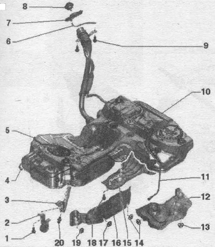


1. Bolt.

1. Bolt.
2. Muffler suspension.
3. Bandage.
4. Fuel line: from the fuel filter to the engine; don't overdo it; clipped to fuel. tank; to disconnect, press the fitting lock.
5. Fuel line; only for vehicles with independent heating: to the independent heating metering pump; do not bend: clipped onto the fuel. tank; to disconnect, press the fitting lock.
6. Overflow hose: hung on the bumper bracket.
7. Rubber bowl.
8. Lid; tighten until it clicks: attached to the fuel filler cap assembly. tank using a clamp.
9. Bolt: for fastening the fuel filler neck. tank; to remove electrostatic discharge; 20 Nm.
10. Fuel tank.
11. Ventilation hose; to the activated carbon absorber; don't overdo it; to disconnect, press the fitting lock; clipped to fuel. tank.
12. Heat shield fuel. tank.
13/14. Nut: 2 Nm.
15. Stand.
16. Heat shield fuel. tank.
17. Nut: 2 Nm.
18. Bolt: 20 Nm.
19. Nut: 2Nm.
20. Expansion piston.


Flange cover - tightening torque


Tighten the arrow bolts to 1.5 Nm.

Fuel delivery module and fuel level sensor installation diagram
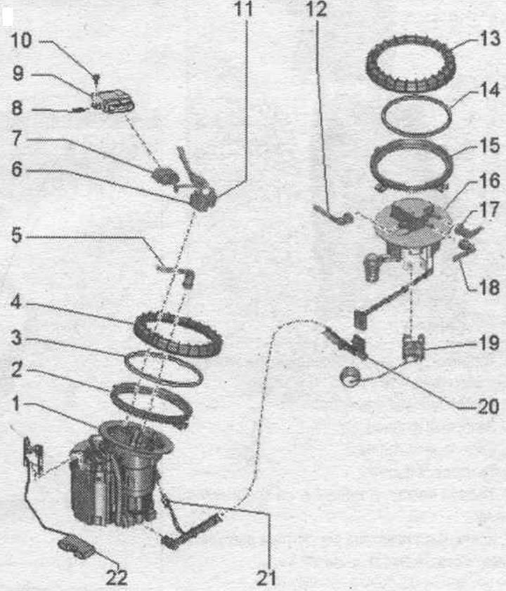


1. Fuel supply unit: after installation, fill the car with at least 5 liters of fuel.

1. Fuel supply unit: after installation, fill the car with at least 5 liters of fuel.
2. Threaded ring.
3. Lip seal: replace: install dry.
4. Union nut: replace; 120 Nm; removal and installation using the T40068 A socket wrench.
5. Fuel line to the engine; don't overdo it; to disconnect from the flange, press the fitting lock; clipped to fuel. tank.
6. Electrical plug connection: for fuel injection. pump "G6" and fuel level sensor "G".
7. Electrical plug connection of the fuel control unit. pump "J538".
8. Bracket.
9. Fuel control unit. pump "J538".
10. Bolt: 2.5 Nm.
11. Electrical plug connection: for fuel level sensor 2 "G169".
12. Ventilation hose: to the activated carbon absorber; don't overdo it; to disconnect from the flange, press the fitting lock; clipped to fuel. tank.
13. Union nut: replace; 120 Nm; removal and installation using the T40068 A socket wrench.
14. Lip seal: replace; install dry.
15. Threaded ring.
16. Shut-off flange: to fuel level sensor 2 "G169".
17. -
18. Ventilation hose: To disconnect from the flange, press the fitting lock; clipped to fuel. tank.
19. Fuel level sensor 2 "G169": after installation, fill the car with at least 5 liters of fuel.
20. Suction pipe: after installation, fill the car with at least 5 liters of fuel.
21. Electrical plug connection: for fuel level sensor 2 "G169".
22. Fuel level sensor "G".


Removal and installation the suction line.


Removing the fuel supply unit. Remove fuel level sensor 2 "G169". Remove fuel level sensor 2 "G169" "pos. 3" together with the suction line "1" from the fuel hole. tank. When removing, ensure that the float of fuel level sensor 2 "G169" does not bend. Disconnect the plug "2" by pressing the lock "arrow A". Squeeze the clamp with pliers "arrow B" and remove the suction line.
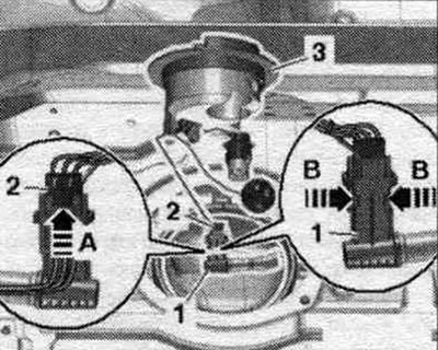
Removing the fuel supply unit. Remove fuel level sensor 2 «G169». Remove fuel level sensor 2 «G169»…


Installation


Installation in reverse order. Prepare suction line "6" for installation. The plug connector "5" must be installed on the suction line "6" as shown in the figure. The plug connectors "2" and the suction line must be secured with 7 cable ties "pos. 3, 4, 7, 8". A seal must be installed. ring "1" on the suction line.
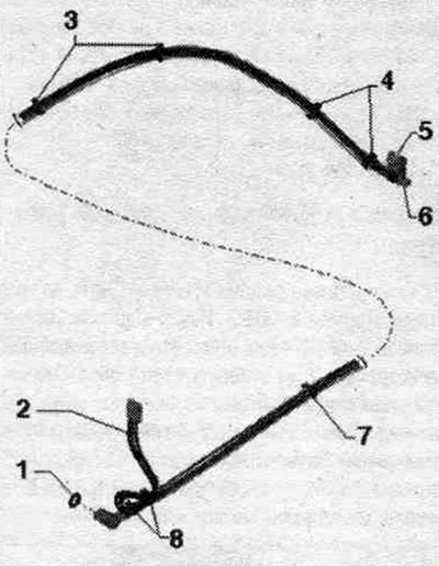
Installation in reverse order. Prepare suction line «6» for installation. The plug connector «5»…


Install the suction line "1" until it clicks into place. Connect plug connector "2" and make sure it is securely fastened. Work carefully so as not to bend the float of the fuel level sensor 2 "G169" "pos. 3". Route the suction line from the trunk to the fuel hole. tank. Install the new sealing cuff over the flange and insert it into the groove on the fuel tank. tank. Insert your hand into the front opening of the fuel tank. tank and install the suction line in the mont. position. Install fuel level sensor 2 "G169". Install the fuel delivery module. Connect the battery, observing the precautions after connecting the battery. After installing the intake manifold, add at least 5 liters of fuel to the vehicle. Cars with independent heater: for fuel ventilation. turn on the independent heater at full power for 10 minutes from the main line to the dosing pump.


Fuel filter
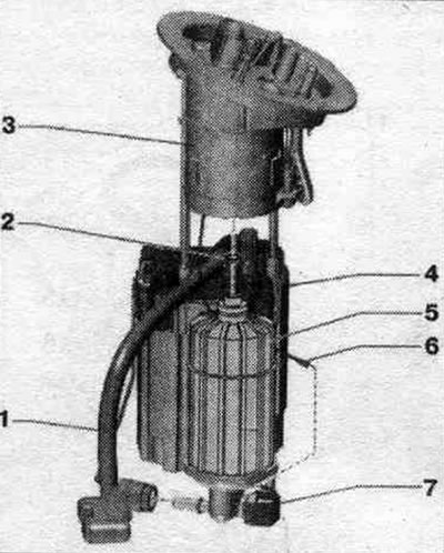


1. Fuel line: To disconnect, press the fitting lock.

1. Fuel line: To disconnect, press the fitting lock.
2. Sealing ring: replace.
3. Shut-off flange.
4. Fuel supply unit.
5. Fuel filter.
6. Ground cable: Install on the mounting plate.
7. Fuel pressure regulator mounting plate: with ground connection.


Dismantling


Removing the fuel supply unit. Disconnect the ground connection "arrow" from the fuel pressure regulator mounting plate.
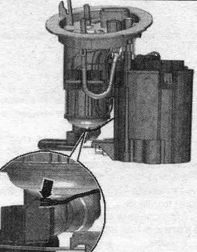
Removing the fuel supply unit. Disconnect the ground connection «arrow» from the fuel pressure…


Disconnect fuel line "1" by pressing the release button. Disconnect the plug connector "6" of the fuel pressure sensor "G". Disconnect the fuel plug connector. pump from pump. Remove flange "4" together with the fuel filter from the fuel supply module "3" in an upward direction. Unlock the 3 locking pins "5" by inserting the 3 release strips "7" (included in the fuel parts kit. filter) "arrow". Remove fuel. filter "2" from the flange downwards.
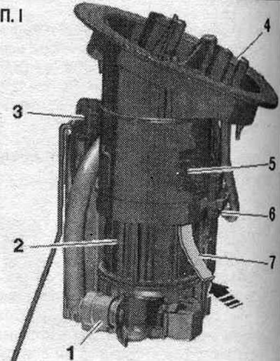


Disconnect fuel line «1» by pressing the release button. Disconnect the plug connector «6» of the…


Installation


Installation in reverse order. Replace the seal. ring. Insert fuel. filter into the guides on the flange and press until it clicks. The fuel filter is installed in one position. Install the fuel delivery module.

Removal air from the system. nutrition


Thanks to the special design of the engine and fuel. pump built into the fuel. tank, remove air from the system. no power supply required. When the starter is turned on, air is removed from the system. automatically.

Activated carbon absorber
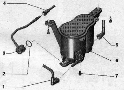


1. Ventilation hose: to the electromagnetic valve 1 of the activated carbon absorber «N80»; to…

1. Ventilation hose: to the electromagnetic valve 1 of the activated carbon absorber "N80"; to disconnect, press the fitting lock; fixed under the bottom on brackets.
2. Sealing ring.
3. Valve.
4. Ventilation hose: from the fuel tank; to disconnect, press the fitting lock.
5. Ventilation duct: exits to the outside under the rear left fender liner.
6. Activated carbon absorber; installation location: in the rear left part of the car underbody under the trim.
7. Bolt: 16 Nm.


Dismantling


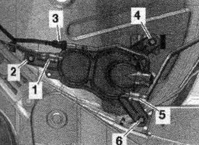
Remove the rear left underbody trim. Disconnect ventilation line "1" by pressing the release button. Disconnect the ventilation line "3" going to the fuel. tank by pressing the release button. Disconnect the ventilation line "5" going to the el. magnetic valve 1 of the activated carbon absorber "N80" by pressing the release button. Unscrew bolts "2, 4, 6" and remove the activated carbon absorber.
Remove the rear left underbody trim. Disconnect ventilation line «1» by pressing the release…


Installation


Installation in reverse order: push the ventilation lines until they click into place.
The article was checked by auto expert Timur Bazhenov
This article is available at russian, bulgarian, belarusian, ukrainian, serbian, croatian, romanian, polish, slovak, hungarian

Share information:
Previous articles
Audi A4 B8: Fuel system (petrol)
Next articles

Fuel tank with attachments, front-wheel drive
Gas pedal — removal and installation


Similar articles on other Audi car models:
Driving with all-wheel drive Audi 80 B3 (1986-1991, petrol)
Fuel Pump Drive Belt — Removal, Inspection and Installation Audi 100 C3 (1982-1990, diesel)
Changing the oil in the Haldex clutch of all-wheel drive models Audi A3 Type 8L (1996-2003)
Remote control fuel tank flap Audi A6 C5 (1997-2004)
Fuel expansion tank Audi A8 D2 (1994-2002)
Fuel tank with attachments Audi Q5 Type 8R (2008-2017)
20 liter fuel tank with attachments Audi A2 (1999-2005)
Link to this page in different formats


Visitor comments

No comments yet


How much will 22 + 19 =


A4(B8, 2007-2015) 
  • General information
  • Operating instructions
  • Power unit
  • Petrol engines 1.8 l
  • Petrol engines 1.8/2.0 l
  • Petrol engines 3.0 l
  • Petrol engines 3.2 l
  • Fuel system (petrol)
  • Diesel engines 2.0 l (CA*)
  • Diesel engines 2.0 l (CJCB)
  • Diesel engines 2.7/3.0 l
  • Diesel engines 3.0 l
  • Fuel system (diesel)
  • Transmission
  • Manual gearbox 0B1
  • Manual gearbox 0B2
  • Manual gearbox 0B3
  • Manual gearbox 0B4
  • Automatic transmission 0B5
  • Automatic transmission 0B6
  • Automatic transmission 0AW
  • All-wheel drive system
  • Chassis
  • Front suspension
  • Rear suspension
  • Brake system
  • Steering system
  • Body
  • Exterior
  • Interior
  • Seats
  • Doors, locks and windows
  • Security system
  • Heating and air conditioning
  • Electrical equipment
  • Audio system
  • Power devices
  • Equipment and devices
  • Lighting and lamps
  • Electrical circuits
 
A4(B7, 2004-2008) 
  • General information
  • Introduction to manual
  • Troubleshooting
  • Operating instructions
  • Maintenance
  • Power unit
  • Petrol engines 2.0 (ALT)
  • Petrol engines 2.0 (TFSI)
  • Petrol engines 1.8 (MPI)
  • Diesel engines
  • Cooling system
  • Air conditioner
  • Fuel and exhaust system
  • Ignition system
  • Starting and charging
  • Transmission
  • Clutch
  • Manual gearbox
  • Automatic gearbox
  • Drive shafts
  • Chassis
  • Brake system
  • Front suspension
  • Rear suspension
  • Steering
  • Body
  • Exterior
  • Interior
  • Electrical equipment
  • Equipment and devices
  • Lighting and signaling
  • Windscreen wipers and washers
  • Electrical diagrams
  • Electrical diagrams (since 2007)
 
A4(B6, 2000-2006) 
  • General information
  • Vehicle Description
  • User manual
  • Maintenance
  • Power unit
  • Gasoline engine
  • Diesel engine
  • Lubrication system
  • Cooling system
  • Supply system
  • Injection system
  • Exhaust system
  • Ignition and control
  • Transmission
  • Gear box
  • Clutch and drive shafts
  • Chassis
  • Brake system
  • Car suspension
  • Steering
  • Body
  • Heating and ventilation
  • Exterior (external elements)
  • Interior (internal elements)
  • Electrical equipment
  • Power devices
  • Lighting and appliances
  • Electrical circuits
 
A4(B6, 2000-2006, petrol) 
  • General information
  • Introduction to the guide
  • Car care
  • Power unit
  • Engine repair
  • Lubrication system
  • Cooling system
  • Injection and control system
  • Ignition system
  • Power and exhaust system
  • Transmission
  • Clutch and drive shafts
  • Car gearbox
  • Chassis
  • Suspension and wheels
  • Steering
  • Brake system
  • Body
  • Interior
  • Exterior
  • Electrical equipment
  • Equipment and devices
  • Lighting and signaling
  • Power devices
  • Electrical circuits
 
A4(B5, 1994-2001) 
  • General information
  • Introduction to the guide
  • Car care
  • Maintenance (gasoline)
  • Maintenance (diesel)
  • Power unit
  • Gasoline engines
  • Diesel engines
  • Engine overhaul
  • Cooling system
  • Fuel injection (gasoline)
  • Fuel system (diesel)
  • Exhaust system
  • Ignition system
  • Transmission
  • Clutch
  • Mechanical gearbox
  • Automatic gearbox
  • Drive shafts
  • Chassis
  • Brake system
  • Car suspension
  • Steering
  • Body
  • Exterior
  • Interior
  • Doors, locks and windows
  • Heating and ventilation
  • Electrical equipment
  • Power devices
  • Equipment and devices
  • Electrical circuits
 
A4(B5, 1994-2001, petrol) 
  • General information
  • Vehicle description
  • Maintenance
  • Power unit
  • Engine repair
  • Turbocharging
  • Exhaust system
  • Cooling system
  • Ignition system
  • Fuel system
  • Motronic injection system
  • MPI and MPFI injection system
  • Transmission
  • Clutch
  • Gearbox and shafts
  • Chassis
  • Steering
  • Car suspension
  • Brake system
  • Wheels and tires
  • Body
  • Heating and ventilation
  • Body parts
  • Electrical equipment
  • Fuses and relays
  • Power devices
  • Lighting and lamps
  • Tools and devices
  • Electrical circuits
 
AudiManual.ru © 2017-2026 · Mobile version · Feedback · Sitemap: EN BG BY UA RS HR RO PL SK HU · Site search · News and articles
80 B2 · 80 B3 petrol · 80 B3 · 80 B4 · 100 C3 diesel · 100 C3 petrol · 100 C3 · 100 C4 petrol · 100 C4 · A3 Type 8L · A4 B5 petrol · A4 B5 · A4 B6 petrol · A4 B6 · A4 B7 · A4 B8 · A6 C4 · A6 C5 · A6 C5 Allroad · A8 D2 · Q5 Type 8R · Q7 Typ 4L · Audi A2 ·
This site uses cookies 🍪. Click the button to accept this fact.