



Table of contents: Components of a radio ↓ Audio system device, Sedan ↓ Audio system device, Avant ↓ A. Multi-pin connector, 8-pin (T8k) ↓ D. Multi-pin connector, 8-pin (T16I) ↓ Concert/Symphony System Connectors ↓ 1. Antenna output (AM/FM1/FM2) ↓ 2. Multi-pin connector, 10-pin (T10v) ↓ 4. Connection block with 4 multi-pin… ↓ Display connectors ↓
Components of a radio
Chorus radio: Radio with built-in CD-npo-player, Audio system: basic, Low display, Mobile phone connection kit. phone.
Concert radio: Radio with built-in CD player (mp3). Basic plus audio system, Mid display, mobile phone connection kit. phone, SD memory card reader. Optional: Audio systems: Standard/Bang & Olufsen, Preparation for installation of mobile. phone, Digital radio "R147" integrated into concert, Output for external audio sources "R199".
Symphony radio: Radio with built-in CD changer, Basic plus audio system, Mid display, SD memory card reader, Mobile phone connection kit. phone. Optional: Audio systems: Standard/Bang & Olufsen, Preparation for installation of mobile. phone, Digital radio "R147" integrated into symphony, Output for external audio sources "R199".
Data transfer to other vehicle systems is carried out via the Infotainment CAN bus and the J533 data bus diagnostic interface.
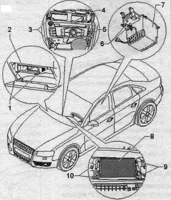
1. Radio remover "T10057".
2. Output for external audio sources "R199".
3/5. Bolt: 3 Nm.
4. Radio "R".
6. Connecting external audio sources "R199" (AUX-ln).
7. Box.
8. Used control indicator. and indication, front "J685".
9/10. Bolt: 2 Nm.
Audio system device, Sedan
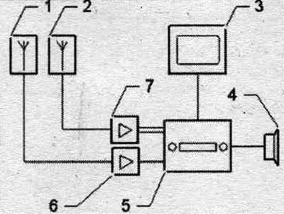
1. Digital antenna, radio "R183" on the right side of the rear window.
2. Antenna "R11" is installed in the rear window.
3. Indicator of used control body. and indication, front "J685" in front panel.
4. Acoustic systems.
5. Radio "R" in the dashboard.
6. Antenna amplifier 2 "R111" behind the right trim of the D-pillar.
7. Antenna amplifier 3 "R112" behind the left trim of the D-pillar.
Audio system device, Avant
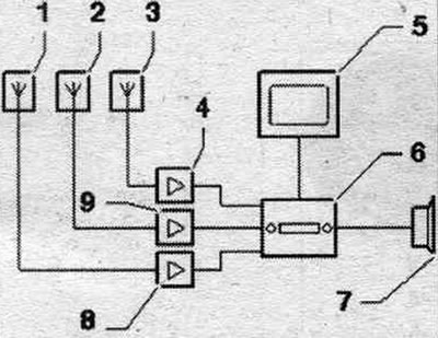
1. Digital antenna, radio "R183" in the glass of the right side door.
2. Rear antenna. 1 "R130" glass is installed in the rear window.
3. Antenna "R11" is installed in the glass of the left side door.
4. Antenna amplifier 3 "R112" behind the left trim of the C-pillar.
5. Used control indicator. and indication, front "J685" in front panel.
6. Radio "R" in the dashboard.
7. Acoustic systems.
8. Antenna amplifier 2 "R111" behind the right trim of the D-pillar.
9. Antenna amplifier "R24" behind the upper trunk trim.
Chorus electrical connectors
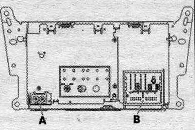
A. Conclusion (AM/FM1/FM2)
B. Connection block with 4 multi-pin connectors.
Unspecified plug contacts are not used.
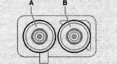
A. Antenna output (AM/FM1/FM2).
Sedan
A. Chamber 2 (AM/FM1) of antenna amplifier 3 "R112" (antenna "R11").
B. Chamber 1 (FM2) of antenna amplifier 3 "R112" (radio antenna 2 "R93").
Avant
A. Chamber 2 (AM/FM1) of antenna amplifier 3 "R112" (antenna "R11").
B. Chamber 1 (FM2) of antenna amplifier "R24" (radio antenna 2 "R93").
B. Connection block with 4 multi-pin connectors
A. Multi-pin connector, 8-pin (T8k)
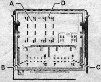
1. Rear right speaker (+).
2. Front right speaker (+).
3. Front left speaker (+).
4. Rear left speaker (+).
5. Rear right speaker (-).
6. Front right speaker (-).
7. Front left speaker (-).
8. Rear left speaker (-).
V. is not involved
C. Multi-pin connector, 12-pin (T12a)
1. Microphone input (-).
2. NF-Out on the right.
3. NF-Out mass.
4. Microphone output (-).
5. NF-ln on the left (-).
6. Low frequency output (-) of the mobile connection kit. telephone/telephone transceiver "R36".
7. Microphone input (+).
8. NF-Out on the left.
9. Microphone output (+).
10. Low-frequency output for short-term microphone muting of the mobile phone connection kit. phone.
11. NF-ln on the left (+).
12. Low-frequency output (+) of the mobile connection kit. telephone/telephone transceiver "R36".
D. Multi-pin connector, 8-pin (T16I)
9. CAN-Infotainment High.
10. CAN-Infotainment Low.
11. Power supply to the indicating device per. used with indication and information "J685".
12. Terminal 31.
13. CAN bus (display) to the front indicator of the used control unit. and indication "J685".
14. CAN bus (display) to the front indicator of the used control unit. and indication "J685".
15. Terminal 30.
16. Constant plus (not used).
Concert/Symphony System Connectors
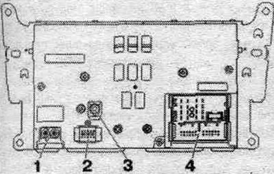
1. Conclusion (AM/FM1/FM2).
2. Multi-pin connector, 10-pin (T10v) to the front indicator of the used control panel and indication "J685".
3. Output (DAB) from antenna amplifier 2 "R111".
4. Connection block with 4 multi-pin connectors.
1. Antenna output (AM/FM1/FM2)
Sedan
A. Chamber 2 (AM/FM1) of antenna amplifier 3 "R112" (antenna "R11").
B. Chamber 1 (FM2) of antenna amplifier 3 "R112" (radio antenna 2 "R93").
Avant
A. Chamber 2 (AM/FM1) of antenna amplifier 3 "R112" (antenna "R11").
B. Chamber 1 (FM2) of antenna amplifier "R24" (radio antenna 2 "R93").
2. Multi-pin connector, 10-pin (T10v)
All contacts are connected to the indicator of the used control body. and indication, front "J685".

1. Power supply.
2. Mass.
3. Not busy.
4. Diagnosis Display.
5. Diagnostic cable.
6. LVDS out (+).
7. LVDS out (-).
8. LVDS out mass.
9. Diagnostic TO.
10. Diagn. T1.
4. Connection block with 4 multi-pin connectors
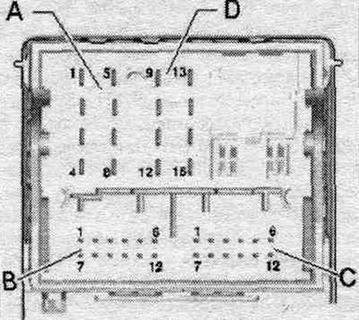
A. Multi-pin connector. 8-pin (T8k)
1. Rear right speaker (+).
2. Front right speaker (+).
3. Front left speaker (+).
4. Rear left speaker (+).
5. Rear right speaker (-).
6. Front right speaker (-).
7. Front left speaker (-).
8. Rear left speaker (-).
B. Multi-pin connector, 12-pin (T12s)
1. Low frequency input (left) from the output for external audio sources "R199".
2. Low frequency input (ground) from the output for external audio sources "R199".
7. Low-frequency input (right) from the output for external audio sources "R199".
C. Multi-pin connector, 12-pin (T12a)
1. Microphone input (-).
2. NF-Out on the right.
3. NF-Out mass.
4. Microphone output (-).
5. NF-ln on the left (-).
6. Low frequency output (-) of the mobile connection kit. telephone/telephone transceiver "R36".
7. Microphone input (+).
8. NF-Out on the left.
9. Microphone output (+).
10. Low-frequency output for short-term microphone muting of the mobile phone connection kit. phone.
11. NF-ln on the left (+).
12. Low-frequency output (+) of the mobile connection kit. telephone/telephone transceiver "R36".
D. Multi-pin connector, 8-pin (T16I)
9. CAN-lnfotainment High.
10. CAN-Infotainment Low.
12. Terminal 31.
15. Terminal 30.
16. Constant plus (not used).
Display connectors
Indicator of the control unit of the control and indication device, front "J685"
Unspecified plug contacts are not used.
Chorus (T10u)
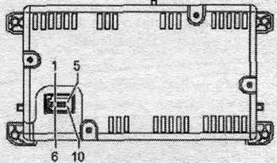
1. CAN bus (display) from the "R" radio.
2. CAN bus (display) from the "R" radio.
3. Radio power connector "R".
4. Terminal 31.
Concert/symphony (T10w)
All contacts are connected to the "R" radio.
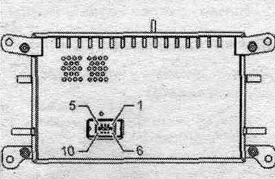
1. Power supply.
2. Mass.
3. Not busy.
4. Diagnosis Display.
5. Diagnostic cable.
6. LVDS out (+).
7. LVDS out (-).
8. LVDS mass.
9. Diagnostic TO.
10. Diagn. T1.