



Installation diagram MMI basic/basic plus Navigation
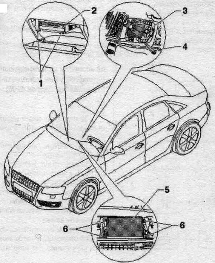
1. Radio remover "T10057".
2. Used front panel control, indication and information output - J523-.
3. Governing body. syst. multimedia "E380".
4. Wedge "3409".
5. Used control indicator. and indication, front "J685".
6. Bolt: 2 Nm.
Multimedia interface installation diagram (until calendar week 44/08)
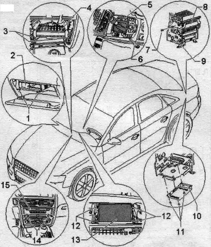
1. Radio remover "T10057".
2. Output for external audio sources "R199".
3. Bolt: 2 Nm; bolt fastening: 2 Nm.
4. Used front panel control, indication and information output "J523".
5. Governing body. syst. multimedia "E380".
6. Wedge "3409".
7. Bolt (2 pcs.): 4.5 Nm.
8. Radio "R".
9. Bracket.
10. Digital radio "R147".
11. Bolt: 4.5 Nm.
12. Bolt: 2 Nm.
13. Used control indicator. and indication, front "J685".
14. Radio remover "T10057".
15. CD changer "R41".
Multimedia interface installation diagram (from calendar week 45/08)
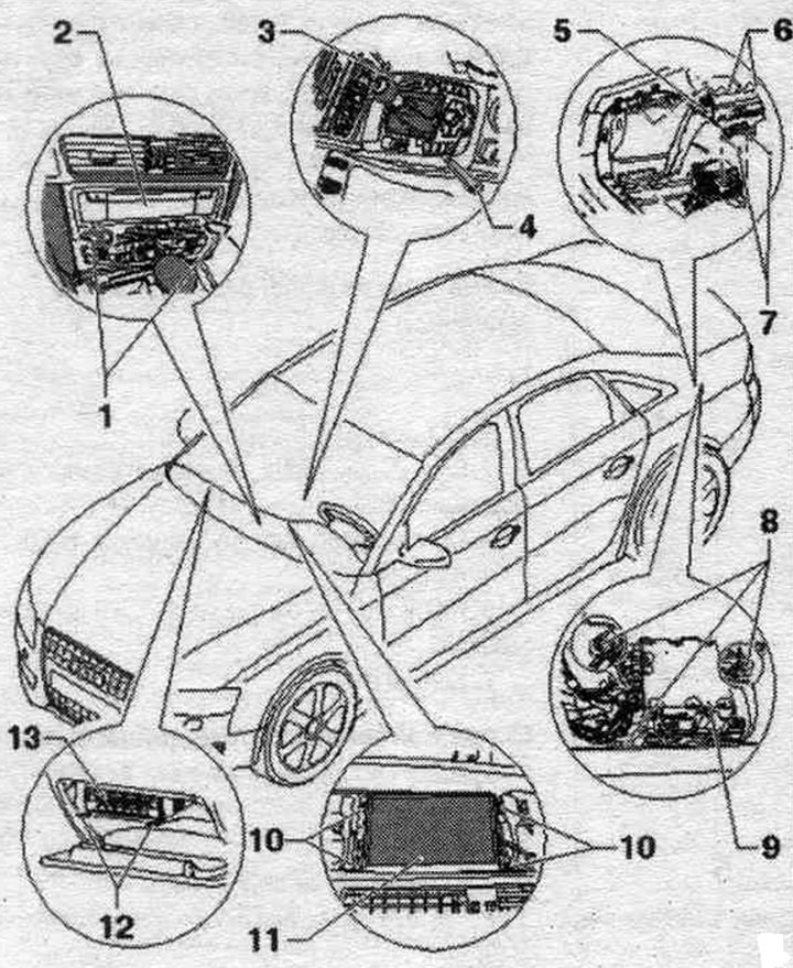
1. Radio remover "T10057".
2. Used communications electronics 1 "J794".
3. Governing body. syst. multimedia "E380".
4. Wedge "3409".
5. Holder.
6/8. Nut: 3.5 Nm.
7. Bolt: 3.5 Nm.
9. Radio "R".
10. Bolt: 2 Nm.
11. Used control indicator. and indication, front "J685".
12. Radio remover "T10057".
13. CD-changer "R41" Output for external audio sources "R199" (interface).
The article is a reprint of material from: Audimanual.ru