
Table of contents: Multimedia system control unit "E380" ↓ Plug connectors of the "R" radio… ↓ Plug connectors for the "R" MMI… ↓ Digital plug connectors for the R147… ↓
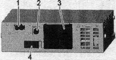
Multimedia system control unit "E380"
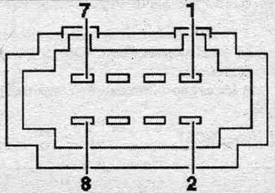
Multi-pin connector, 16-pin (T16c)
All contacts are connected to the control unit. per. indication and control module. inform, system "J523".
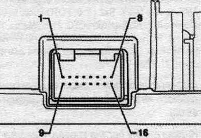
6. Wake UP signal.
7. Power supply.
8. Mass.
13. Res HU signal.
14. Res BT signal.
15. Entrance.
16. Exit.
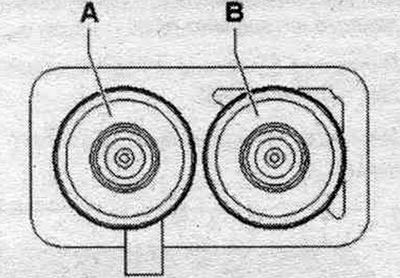
Plug connectors of the "R" radio multimedia interface (until calendar week 44/08)
Radio "R"
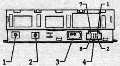
1. High frequency output from antenna amplifier 3 "R112".
2. Output of intermediate frequency to antenna amplifier 3 "R112".
3. MOST bus.
4. Multi-pin connector, 8-pin (T8m).
3. MOST bus
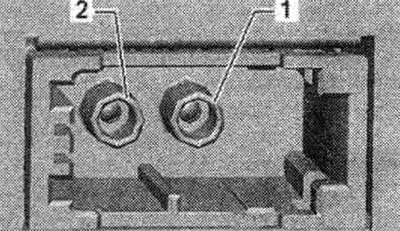
1. Entrance.
2. Exit.
4. Multi-pin connector, 8-pin (T8m)
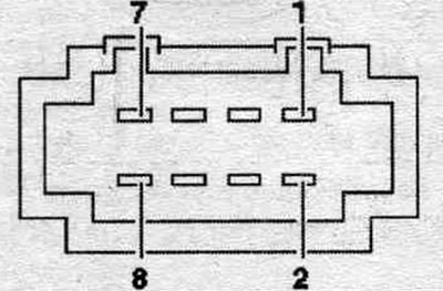
1. Terminal 31.
2. Terminal 30.
5. Diagnostic cable for ring break.
Plug connectors for the "R" MMI radio (from calendar week 45/08)
Radio "R"
1. Conclusion (AM/FM1/FM2).
2. Connector (DAB) of antenna amplifier 2 "R111" (for Europe only).
3. Connection block with 4 multi-pin connectors.
4. MOST bus.
1. Antenna output (AM/FM1/FM2)
Sedan
A. Camera 2 (AM/FM1) from antenna amplifier 3 "R112" (radio antenna 2 "R93").
B. Chamber 1 (FM2) of antenna amplifier 3 "R112" (antenna "R11").
Avant
A. Camera 2 (AM/FM1) from antenna amplifier 3 "R112" (radio antenna 2 "R93").
B. Chamber 1 (FM2) from antenna amplifier "R24" (antenna "R11").
3. Connection block with 4 multi-pin connectors
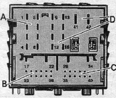
A. Multi-pin connector, 8-pin (T8ag)
1. Rear right speaker (+).
2. Front right speaker (+).
3. Front left speaker (+).
4. Rear left speaker (+).
5. Rear right speaker (-).
6. Front right speaker (-).
7. Front left speaker (-).
8. Rear left speaker (-).
B. Multi-pin connector, 12-pin (T12w)
17. NF-ln on the left.
18. NF-ln mass.
19. NF-ln diagnostics.
21. NF Diagnostics.
22. NF (-) mobile connection kit. Telephone.
23. NF-ln on the right.
24. NF-ln screen mass.
27. NF Screen mass.
28. NF (+) mobile connection kit. phone.
C. Multi-pin plug connection, 12-pin
29. Headphone output 1 diagnostics.
31. Headphone output 1/2 diagnostics.
34. Headphone output 2 diagnostics.
35. Headphone output 1 left.
36. Headphone output 1 mass.
37. Headphone output 1 right.
38. Headphone output 2 left.
39. Headphone output 2 ground.
40. Headphone output 1 right.
D. Multi-pin connector, 10-pin (T10ag)
9. Subwoofer in the rear. shelf "R157".
10. Central midrange and tweeter "R158".
11. Ring break diagnostic cable.
13. Subwoofer in the rear. shelf "R157".
14. Central midrange and tweeter "R158".
41. Terminal 31.
42. Terminal 30.
4. MOST bus
1. Entrance.
2. Exit.
Digital plug connectors for the R147 multimedia interface radio (until calendar week 44/08)
Digital radio "R147"
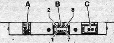
A. Output (DAB) from antenna amplifier 2 -Rill-.
B. Multi-pin connector, 8-pin (T8o).
S. Shina MOST.
B. Multi-pin connector, 8-pin (T8o)
1. Terminal 31.
2. Terminal 30.
5. Diagnostic cable for ring break.
S. Shina MOST
1. Entrance.
2. Exit.
[Material republished from the website AUDIMANUAL]