
Table of contents: Front control panel control unit,… ↓ D. 4-pin multi-pin connector block ↓ Multimedia Interface connectors… ↓ Multimedia Interface connectors… ↓ MMI minimum equipment ↓ 2. Connection block with 4 multi-pin… ↓ 3. MOST bus ↓ 5. Multi-pin connector, 4-pin (T4al) ↓ 6. Multi-pin connector, 4-pin (T4ap) ↓ MMI top-of-the-line ↓ 2. Connection block with 4 multi-pin… ↓ 5. Multi-pin connector, 4-pin (T4am) ↓
Front control panel control unit, display and information output "J523"
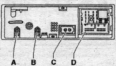
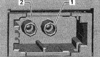
A. High frequency output from antenna amplifier 3 "R112".
B. Output of intermediate frequency to antenna amplifier 3 "R112".
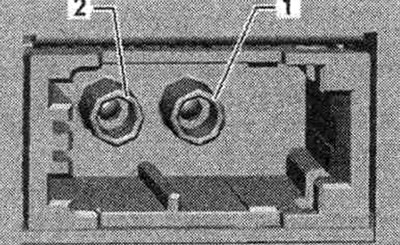
S. Shina MOST.
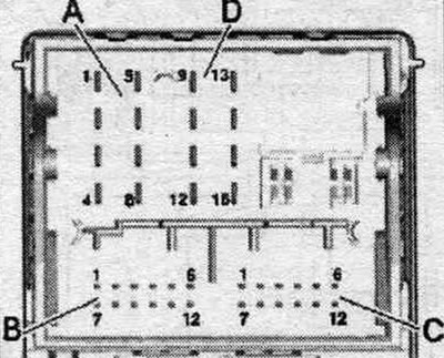
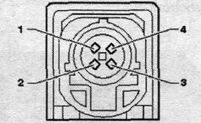
D. Connection block with 4 multi-pin connectors.
Unspecified plug contacts are not used.
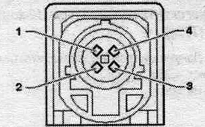
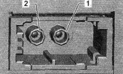
S. Shina MOST
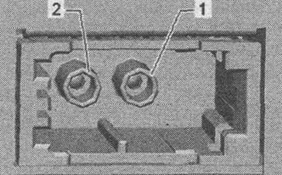
1. Entrance.
2. Exit.
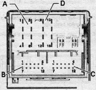
D. 4-pin multi-pin connector block
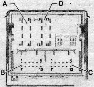
A. Multi-pin connector, 8-pin (T8ab)
1. Wake UP (start) to the control panel, multimedia system. "E380".
4. Res HU to the control device. multimedia system. "E380".
5. Res VT (load test) to the control device. multimedia system. "E380".
8. Ground to the flasher indicator device. used with indication and information "J685".
B. Multi-pin connector, 12-pin (T12q)
1. Data to the control device. multimedia system. "E380".
2. Not busy.
3. Data (+) to the indicating device per. used with indication and information "J685".
4. Data (-) to the indicating device per. used with indication and information "J685".
5. Data from the governing body. syst. multimedia "E380".
C. Multi-pin connector, 12-pin (T12r)
5. Data (-) from the indicating device per. used with indication and information "J685".
7. Ground to control body. syst. multimedia "E380".
11. Data (+) from the indicating device per. used with indication and information "J685".
D. Multi-pin connector, 8-pin (T16j)
11. Low-frequency output for short-term microphone muting of the mobile phone connection kit. phone.
12. Terminal 31.
13. Power supply to the indicating device per. used with indication and information "J685".
14. Diagnostic cable for ring break.
15. Terminal 30.
16. Power supply of the control body. syst. multimedia "E380".
Multimedia Interface connectors (until calendar week 44/08)
Front control panel control unit, display and information output "J523"
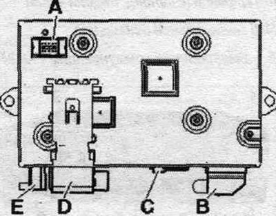
A. 10-pin connector (japanese navigation system).
B. Multi-pin connector, 20-pin (T20b) to the control unit. multimedia system. "E380".
S. Shina MOST.
D. Multi-pin connector, 22-pin (T22a) to the control unit. front panel control, indication and information output "J685".
E. FBAS input from TV tuner "P78"/used rear camera. type "J772".
B. Multi-pin plug connector, 20-pin (T20B)
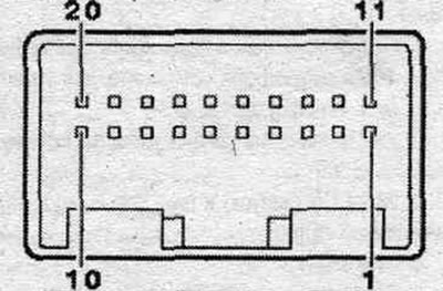
1. Terminal 30.
2. Terminal 31.
3. Ring break diagnostic cable.
6. Wake UP (start) to the control panel, multimedia system. "E380".
7. Power supply of the control body. syst. multimedia "E380".
8. Ground to control body. syst. multimedia "E380".
13. PESET from the governing body. syst. multimedia "E380".
14. PESET to the control body. syst. multimedia "E380".
15. Data to the control device. multimedia system. "E380".
16. Data from the governing body. syst. multimedia "E380".
20. Low-frequency output for short-term microphone muting of the mobile phone connection kit. phone.
S. Shina MOST
1. Entrance.
2. Exit.
Multimedia Interface connectors (from calendar week 45/08)
MMI minimum equipment
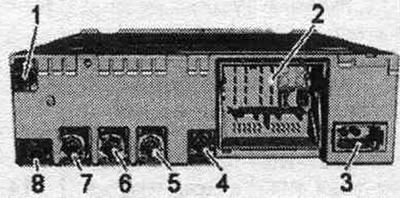
Communications Electronics Control Unit 1 "J794"
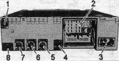
1/4. Not busy.
2. Connection block with 4 multi-pin connectors.
3. MOST bus.
5. Multi-pin plug connector, 4-pin (T4al) to the indicator of the used control body. and indication, front "J685".
6. Multi-pin connector, 4-pin (T4ap) to the terminal for external sources "R199".
7/8. Not busy.
2. Connection block with 4 multi-pin connectors
A. Multi-pin connector, 8-pin (T8ah)
1. Low-frequency output for short-term microphone muting of the mobile phone connection kit. phone.
2. power supply of the control body. syst. multimedia "E380".
3. Wake UP (start) to the control panel, multimedia system. "E380".
4/5. Not busy.
6. Res MU to the control device. multimedia system. "E380".
7. Ring break diagnostic cable.
B. Multi-pin connector, 12-pin (T12x)
8. Microphone input (+) from the microphone unit in front of the roof module "R164" (front left microphone "R140").
9. Microphone input (-) from the microphone unit in front, roof module "R164" (front left microphone "R140").
C. Multi-pin connector, 12-pin (T12u)
All contacts are connected to the output for external audio sources "R199".
1. NF-ln mass.
2. NF-ln on the right.
3. USB (+5 V).
4. USB (ground).
5. Not busy.
6. Detect.
7. NF-ln on the left.
8. NF-ln screen mass.
9. FBAS (+) cable.
10. FBAS cable (-).
11/12. iPod data
D. Multi-pin connector, 8-pin (T16q)
10. Data from the governing body. syst. multimedia "E380".
11. Data to the control device. multimedia system. "E380".
12. Terminal 31.
14. Res VT (load test) from the control device. multimedia system. "E380".
15. Terminal 30.
16. Ground to control body. syst. multimedia "E380".
3. MOST bus
1. Entrance.
2. Exit.
5. Multi-pin connector, 4-pin (T4al)
All contacts are connected to the indicator of the used control body. and indication, front "J685".
1. LVDS (-).
2. LIN.
3. LVDS (+).
4. Mass.
6. Multi-pin connector, 4-pin (T4ap)
All contacts are connected to the output for external audio sources "R199".
1. D (+).
2. iPod identification.
3. D (-).
4. Mass.
MMI top-of-the-line
Communications Electronics Control Unit 1 "J794"
1/4. Not busy.
2. Connection block with 4 multi-pin connectors.
3. MOST bus.
5. Multi-pin plug connector, 4-pin (T4al) to the indicator of the used control body. and indication, front "J685".
6. Multi-pin connector, 4-pin (T4ap) to the terminal for external sources "R199".
7/8. Not busy.
2. Connection block with 4 multi-pin connectors
A. Multi-pin connector, 8-pin (T8ah)
1. Low-frequency output for short-term microphone muting of the mobile phone connection kit. phone.
2. power supply of the control body. syst. multimedia "E380".
3. Wake UP (start) to the control panel, multimedia system. "E380".
4/5. Not busy.
6. Res MU to the control device. multimedia system. "E380".
7. Ring break diagnostic cable.
B. Multi-pin connector, 12-pin (T12x)
8. Microphone input (+) from the microphone unit in front of the roof module "R164" (front left microphone "R140").
9. Microphone input (-) from the microphone unit in front, roof module "R164" (front left microphone "R140").
C. Multi-pin connector, 12-pin (T12u)
All contacts are connected to the output for external audio sources "R199".
1. NF-ln mass.
2. NF-ln on the right.
3. USB (+5 V).
4. USB (ground).
5. Not busy.
6. Detect.
7. NF-ln on the left.
8. NF-ln screen mass.
9. FBAS (+) cable.
10. FBAS cable (-).
11/12. iPod data.
The following contacts are additionally connected to the Internet access control unit "J666" (since 2013 model year)
3. USB (+5 V).
4. USB (ground).
6. Detect
D. Multi-pin connector, 8-pin (T16q)
9. Signal to turn on the phone holder "R126".
10. Data from the governing body. syst. multimedia "E380".
11. Data to the control device. multimedia system. "E380".
12. Terminal 31.
13. DIAG signal from the phone holder "R126".
14. Res VT (load test) from the control device. multimedia system. "E380".
15. Terminal 30.
16. Control body weight. syst. multimedia "E380".
3. MOST bus
1. Entrance.
2. Exit.
5. Multi-pin connector, 4-pin (T4am)
All contacts are connected to the indicator of the used control body. and indication, front "J685".
1. LVDS (-).
2. LIN.
3. LVDS (+).
4. Mass.
6. Multi-pin connector, 4-pin (T4ap)
All contacts are connected to the output for external audio sources "R199"/6/y Internet access "J666" (since 2013 model year).
1. D (+).
2. iPod identification.
3. D (-).
4. Mass.