
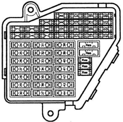
Location of fuses in the box on the instrument panel
Fuse table
| Number | Current (A) | Consumer |
| S1 | 10 | Air conditioner control |
| S2 | 5 | Footwell lights |
| S3 | 5 | Heated spray nozzles |
| S4 | 5 | Radiator fan control |
| S5 | 10 | Oil level gauge, multifunction switch, telephone settings, tire pressure monitoring, rear seat heating, rear window shade |
| S6 | 5 | Pressure sensor, air quality sensor |
| S7 | 10 | Emergency Brake Light Switch, Clutch Pedal Position Sensor, Electronic Vehicle Stability Control Master, Steering Angle Sensor, Electronic Vehicle Stability Control Button |
| S8 | 5 | Telephone |
| S9 | 15 | Vacuum pump (brake booster) |
| S10 | 10 | Automatic headlight beam throw adjustment |
| S11 | 10 | Control unit V30 |
| S12 | 10 | Diagnostic socket |
| S13 | 10 | Power SMLS |
| S14 | 10 | Brake lights |
| S15 | 10 | Combined instrument, navigation |
| S16 | 10 | Not occupied |
| S17 | 10 | Ground clearance, parking safety system, tire pressure monitoring |
| S18 | Not occupied | |
| S19 | 15 | Fog light, rear fog light |
| S20 | 15 | Dipped beam left, manual headlight range adjustment |
| S21 | 15 | Dipped beam right, manual headlight range adjustment |
| S22 | 15 | driver's door |
| S23 | 15 | front passenger door |
| S24 | 30 | Comfort system control |
| S25 | 30 | Heating fan |
| S26 | 30 | Rear window heating |
| S27 | 30 | trailer control |
| S28 | 20 | Fuel pump |
| S29 | 20 | Engine management |
| S30 | 20 | Retractable roof |
| S31 | 15 | Diagnostic socket, electrochromic rearview mirror, reversing lights |
| S32 | 20 | Engine management |
| S33 | 15 | cigarette lighter |
| S34 | 15 | Engine management |
| S35 | 30 | Detachable socket - trunk |
| S36 | 30 | Wiper |
| S37 | 20 | ILM master |
| S38 | 15 | Convenience system control, switch-off button, active sensor, tailgate release button |
| S39 | 20 | Radio |
| S40 | 25 | Sound signal |
| S41 | Not occupied | |
| S42 | 25 | Vehicle Stability Control Control Unit |
| S43 | 15 | Engine management |
| S44 | 30 | seat heating |
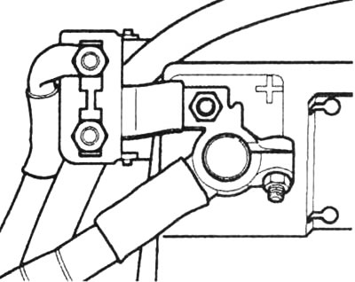
The 150A main fuse is located on the battery
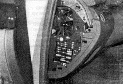
Fuse box in the cabin: The box is located on the left side of the instrument panel. In order to gain access to the fuses, the cover must be removed. On the inside of the cover there is a fuse distribution diagram and plastic tweezers for replacing fuses.
Of course, there may be some changes and deviations in the distribution of fuses, since it depends on the year of manufacture of the car, engine and equipment. On the circuit diagrams, the designation of the fuses, starting with the S23 fuse, is preceded by the number 2 (those. fuse S39 is designated as S239).
The fuse boxes contain fuses, which consist of a transparent plastic part. Two flat pins are embedded in this part, which are interconnected by fusible wire. A blown fuse can be identified by a broken wire. Often, the plastic coating also burns out or breaks out.
The fuse rating can be determined by the color and inscription on the fuse:
- Beige - 5 amps
- Brown - 7.5 amps
- Red - 10 amps
- Blue - 15 amps
- Yellow - 20 amps
- White - 25 amps
- Green - 30 amps
Replacing fuses
1. Before replacing a fuse, turn off the relevant consumer and the ignition. Remove the cover from the fuse box.
2. Using plastic tweezers, remove the defective fuse from the socket.
3. Insert a new fuse with the same rating into the socket. Pay attention to the fuse position.
4. If the fuse immediately blows again, the fuse may be defective, or you may have inserted a fuse with less current than needed. In this case, the cause should be determined immediately. The consumer may be damaged, in the worst case, the insulation of the wire may catch fire.
Visitor comments