
Removal - early models
20. Remove the glove box - see chapter 11. The resistor/fuse block is mounted on the side of the fan housing.
21. Disconnect the two electrical connectors on the side of the unit mounting plate.
22. Squeeze the latches and remove the resistor/fuse assembly from the housing.
Removal - late models
23. Remove the glove box - see chapter 11. The resistor/fuse block is mounted on the rear wall of the motor housing.
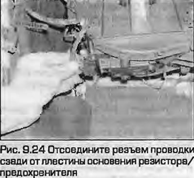
24. Disconnect the electrical connector at the base of the unit (Fig. 9.24).
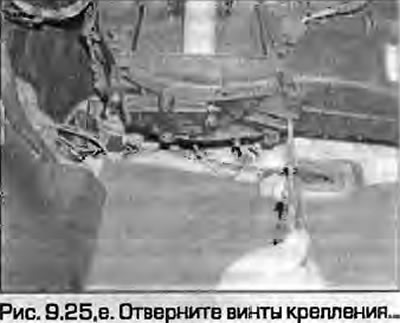
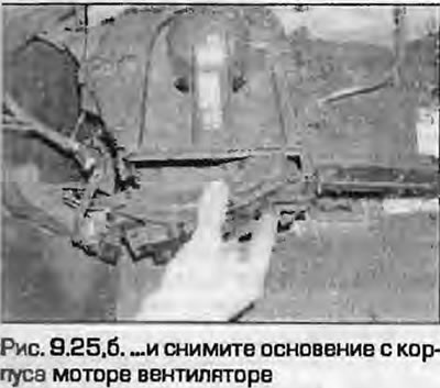
25. Loosen the mounting screws and remove the block base from the motor housing (Fig. 9.25).
 |
 |
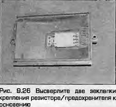
26. Drill out the two rivets securing the resistor/fuse block to the base plate (Fig. 9.26).
27. Release the latches and remove the resistor/fuse assembly from the base.
Installation
28. Installation - reverse procedure. On early models, the bases are secured with pre-prepared screws. On later models, the block is secured to the base with 3.2x10 mm screws.
[The article was copied from the website AUDImanual]