



Table of contents: Removal ↓ Installation ↓
1. The information contained in this paragraph applies only to manual systems without air conditioning. On models with air conditioning, the removal and installation of components is described in paragraph 11.
Removal
2. Disconnect the negative battery cable and remove the center console as described in chapter 11.
3. Remove the radio - see chapter 12.
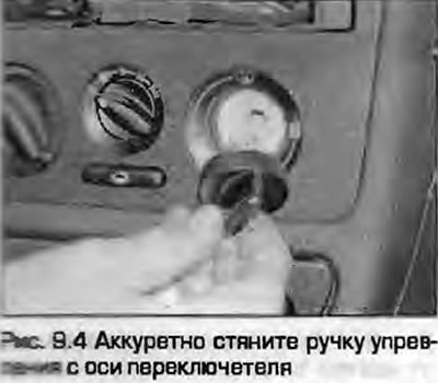
4. Carefully pull the handles off the control switch shafts (Fig. 9.4).
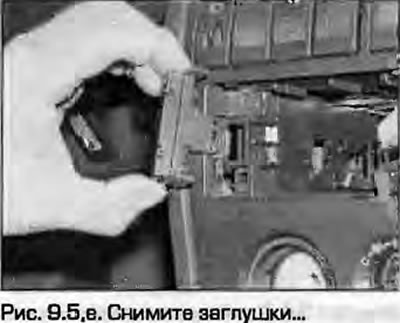
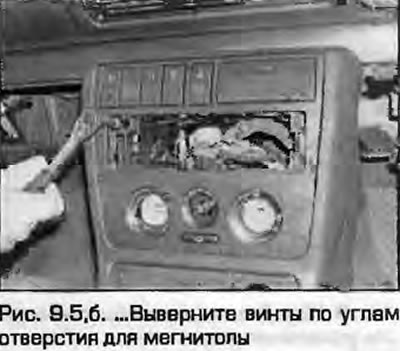
5. Remove the covers, carefully unscrew the screws at the corners of the opening for the radio (fig. 9.5, a, b).
 |
 |
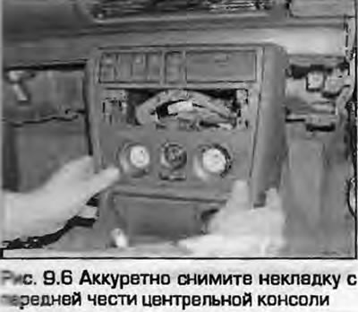
6. Using a small flat-head screwdriver, carefully pry up the front trim panel at the front of the center console (Fig. 9.6). Wrap the screwdriver in tape to prevent scratching the panel.
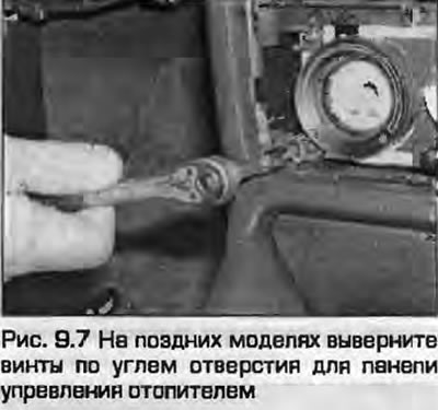
7. On later models, remove the screws at the corners of the heater control unit opening. Note the correct position of the spring clips (Fig. 9.7). B Remove the front section of the center console as described in chapter 11.
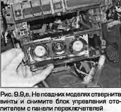
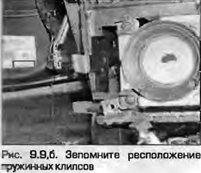
9. Remove the screws and the center console switch panel. The heater control unit can be removed from the back of the switch panel by removing the mounting screws. On later models, there is no need to remove the switch panel as the heater control unit is removed from the front; remember the location of the spring clips (fig. 9.9, a, b).
 |
 |
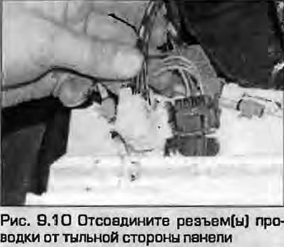
10. Disconnect the wiring connectors from the rear of the panel (Fig. 9.10).
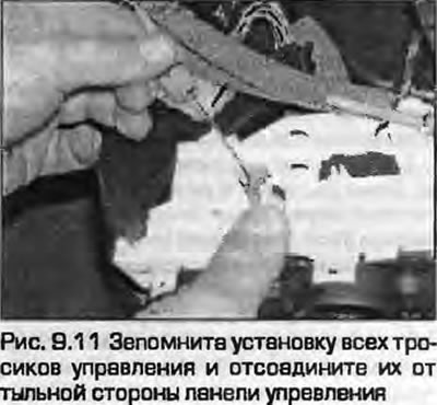
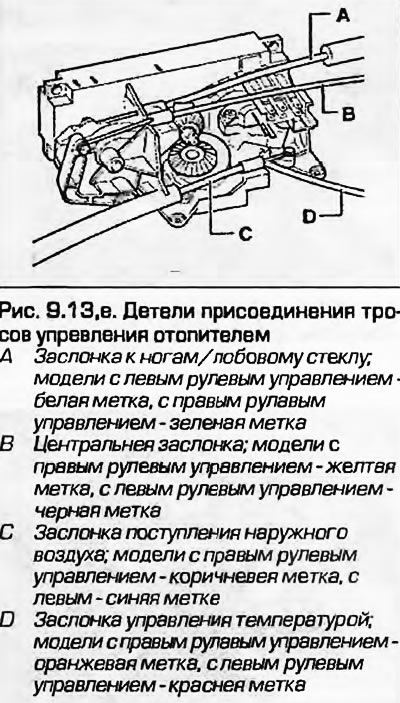
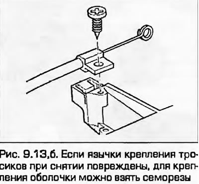
11. Remember the position of each cable (the tips are color coded) and disconnect them from the control panel (Fig. 9.11). The outer shells are held in place by spring clips, which can be ignited with a flat-head screwdriver. Some shells are secured with self-tapping screws.
12. After disconnecting the cables and wiring, remove the control panel from the vehicle.
Installation
13. Installation - reverse procedure. Connect the cables to their places. Before installing the console, check the operation of the controls.
Note: If the spring clamps are damaged or lost during removal, the outer cable sheaths can be secured with self-tapping screws - holes are provided for this purpose (fig. 9.13, a, b).
 |
 |