
Table of contents: General information and safety… ↓ Safety precautions when servicing an… ↓
Heater and air conditioner
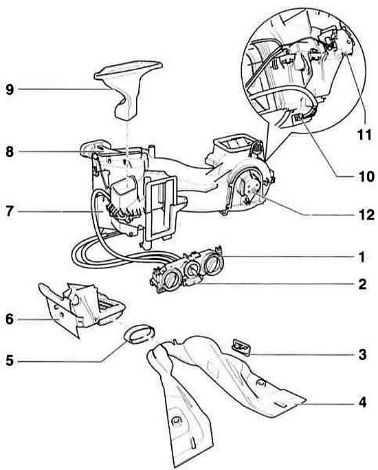
- 1 heater drive
- 2 switch for fresh and ventilation air damper
The switch is rigidly connected to the heater drive and cannot be replaced separately.
- 3 nozzle leg area
- 4 rear passenger compartment heating duct
- 5 connecting element
- 6 nozzle leg area
- 7 heater casing
- 8 heat exchanger
- 9 Upper air duct
- 10 additional fan resistor
- 11 Fresh/recirculated air flap drive motor
- 12 fan
Warning: The switch is illuminated by a light guide and has only one incandescent bulb. To replace the bulb, remove the fan switch. Remove the bulb from the socket with pliers. Since mid-1997, the light-emitting diode (LED) has been replaced. The latter is not replaceable.
Components of the heating, ventilation and air conditioning system located in the passenger compartment of the vehicle
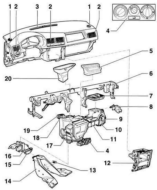
- 1 side window nozzles
- 2 nozzles
- 3 glass defrosting nozzle
- 4 controls for hot and fresh air
- 5 spacer
- 6 instrument panel crossbar
- 7 cabin air dust filter
- 8 Electric motor. Fresh air/ventilation flap
- 9 fresh air fan
- 10 additional resistor. With thermal fuse
- 11 heating device
- 12 central visor
- 13 Air supply nozzle to the foot area
- 14 front channel
- 15 seal
- 16 connecting element
- 17 heater drive rod
- 18 heat exchanger
- 19 Heat exchanger/engine compartment bulkhead joint seal
- 20 spacer for glass defrosting nozzles
Heater housing with elements of the interior heating and ventilation system
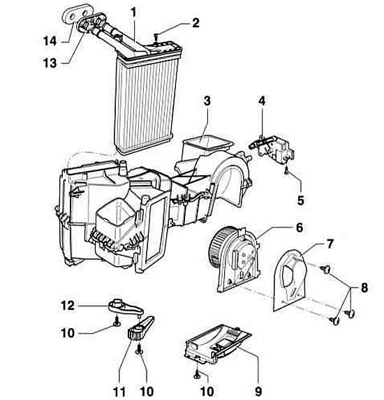
- 1 heat exchanger
After removal, the coolant must be completely replaced.
- 2 self-tapping screws
Required in cases where the heat exchanger locking tabs are broken.
- 3 Air distributor housing. Should not be disassembled.
- 4 Fresh air/circulation flap motor
- 5 self-tapping screws
- 6 fresh air casing
- 7 Fresh air casing cover
- 8 self-tapping screw
- 9 additional resistor. With overheating fuse.
- 10 self-tapping screw
- 11 Central damper lever
- 12 temperature flap lever
- 13th base
- 14 Heat exchanger/engine compartment bulkhead seal
The seal has a mark on the end surface. The seal must be installed so that the meta coincides with the H m marking on the base
Cabin Air Conditioning System Diagram
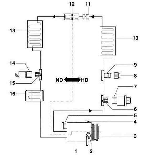
- 1 compressor
- 2 compressor speed sensor
- 3 electromagnetic clutch
- 4 oil drain plug
- 5 safety valve
- 6 connecting element with valve
- 7 High pressure switch. For air conditioner and electromagnetic clutch
- 8 lid. With a seal, must be secured.
- 9 service connection. Near the condenser.
- 10 capacitor
- 11 threaded connection in the coolant line
- 12 throttle. Built into connection –11–.
- 13 evaporator
- 14 Low pressure switch \ coolant circuit
- 15 connecting element with valve
- 16 collection container
- HD high pressure side
- ND low pressure side
Layout of the heating and air conditioning components in the engine compartment
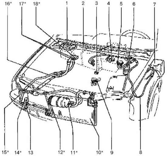
- 1 dust filter
- 2 fairing cover
- 3 evaporator drain valve
- 4 Heater Heat Exchanger Connectors
- 5 air supply mode switching flap (fresh air/closed circulation) (N63)
- 6 Control of the cooling system fan operation (J293)
- 7 vacuum tank
- 8 vacuum hose
- 9 Air Conditioner Temperature Sensitive Switch
- 10 capacitor
- 11 pressure reducing valve
- 12 Air conditioning clutch (N₂5)
- 13 ambient air temperature switch sensor (F38)
- 14 Air conditioning pressure switch (F129)
- 15 receiver-dryer
- 16 viewing window
- 17 low and high pressure service valves
- 18 expansion valve
General information and safety precautions
The air supplied by the ventilation system to the car interior through the filter can be heated or cooled depending on the choice of the driver and passengers. The heater or air conditioner is located in the passenger compartment in the housing under the instrument panel. The entire flow of air supplied to the interior is directed for heating or cooling through the same casing. The temperature and speed of the air flow are regulated using the controls located on the control panel.
The heat generated by the engine is transferred by the coolant to the heater radiator located in the passenger compartment. The air flow supplied by the ventilation system passes through the radiator and is heated by the heat of the engine coolant flowing inside the radiator. The degree of heating is regulated by mixing cold and hot air in a certain ratio using a mixing flap.
The air conditioner in cooling mode removes excess heat and moisture from the passenger compartment in accordance with basic physical principles. The refrigerant, free of FCKW (R 134 a), and not harmful to the environment, circulating as a liquid in the part of the system where high pressure is maintained, evaporates and turns into a gas in the low-pressure section. When the gas expands, cooling occurs, accompanied by the removal of heat from the air supplied by the fan to the passenger compartment and a decrease in its temperature. Then, as it passes through the condenser, the refrigerant gives off the absorbed heat to the surrounding air. The heat removal cycle continues indefinitely as the refrigerant circulates in a closed circuit. Moisture is removed from the air supplied to the passenger compartment due to condensation on the evaporator of the refrigeration chamber.
The air conditioner automatically maintains the set interior temperature constant.
The Climatronic climate control system, unlike a conventional air conditioner, automatically regulates the amount and distribution of air in addition to the temperature. The amount of air is regulated smoothly by changing the number of fan revolutions depending on the temperature difference between the set temperature value and the interior temperature.
Climatronic also has a solar sensor that registers solar radiation. It is located in the centre of the instrument panel under the windscreen. In the case of particularly high solar radiation, the solar sensor automatically influences the speed of the fan via the electronic control system and thus the amount of air supplied to the interior. The set value for the interior temperature is adjusted according to solar radiation.
The compressor is driven by an electric motor.
The electronic control unit is built into the air conditioner control unit. When the fan speed is manually set below the minimum, the heating/air conditioning system is switched off.
Malfunctions that occur in the control device or sensors and actuators are recorded in the control device's fault memory. A special device is used to read fault codes.
The air conditioning system is a potential hazard. When servicing it, certain rules must be followed. Most repair and maintenance operations on the air conditioning system require special equipment and certain skills.
The body ventilation is provided by forming a through air flow. Fresh air enters the car through the air intake located in front of the windshield. The air flow goes out through the exhaust channels located under the rear bumper.
The air flow rate is regulated by a four-speed fan.
The air heating system of the mixing type is designed to quickly respond to changes in the air temperature in the passenger compartment and reduce the pulsation of the heated air temperature. The engine cooling system coolant constantly circulates in the heater radiator and the coolant flow is not regulated. The regulated factor is the air temperature, which is changed by the mixing valve, which determines the amount of air passing through the heater radiator before it enters the car's passenger compartment.
To prevent outside air from entering the car interior, there is an air circulation mode.
Safety precautions when servicing an air conditioner
The air conditioning system must be serviced only by trained technical personnel who are trained in safe operating practices using the proper equipment, observing depressurization rules, and are familiar with the methods of collecting and storing automotive refrigerant.
Avoid contact of refrigerant with skin.
Wear safety glasses when working near the air conditioning system.
If refrigerant gets on your skin or eyes, do not rub the affected area. Rinse immediately with cold water for at least 15 minutes. Seek immediate medical attention or medical attention. Self-medication is not allowed.
The refrigerant in a new cylinder is stored under pressure. Store the cylinder at a temperature not exceeding 50°C. Take measures to prevent the cylinder from falling from a height or other situations that may cause damage to it.
Work should be carried out in a well-ventilated area. The refrigerant evaporates quickly, reducing oxygen supply and making breathing difficult.
The gaseous refrigerant is heavier than air and should collect relatively quickly at a low level, such as under a car.
When refrigerant burns, it produces toxic gas. Keep refrigerant away from open flames. Do not smoke. Avoid inhaling smoke when using a flame leak detector.
When welding near an air conditioning system, exposure to high temperatures or open flames may occur. Overheating may cause pressure in the system to increase and cause a fire.
Cleaning the condenser or evaporator with water vapor is not permitted. Only cold water or compressed air should be used.
A 4-stage fresh air fan is used to increase air exchange. Resistors are connected to ensure that the fan operates at different speeds at individual stages. The resistors are located in the connecting board on the fan. If there are any faults, the connecting board is replaced as a set.
If fresh air should not be sucked in, for example, when the outside air is bad, pressing the recirculation ventilation button switches to air circulation. In this case, the air circulates only inside the passenger compartment. The switch moves the flap, acting on a small electric motor.
Warning: If the "Windshield defrost mode" is activated, i.e. the air distribution switch is set to the end position at the top, recirculation mode is not possible.
Warning: The A3 can also be equipped with air conditioning.
Warning: Air conditioning repair is not described here. This work should be performed in a specialized workshop.
Warning: Do not open the air conditioner cooling circuit, as liquid coming into contact with your skin may cause frostbite.
Warning: If the fluid accidentally comes into contact with your skin, immediately rinse the affected area with cold water for at least 15 minutes. Coolant is colorless and odorless and is heavier than air. If coolant leaks, there is a risk of poisoning in the underbody or lower part of the vehicle (the presence of liquid is not felt).
Warning: If the fluid accidentally comes into contact with your skin, immediately rinse the affected area with cold water for at least 15 minutes. Coolant is colorless and odorless and is heavier than air. If coolant leaks, there is a risk of poisoning in the underbody or lower part of the vehicle (the presence of liquid is not felt).
[The original publication in its entirety is posted on the website: AUDIMANUAL]