
Table of contents: Removal ↓ Installation ↓ Connecting the cables to the heater… ↓ Connecting the cables to the heater… ↓ Adjusting the heater rods ↓
Removal
1. Remove the heater drive.
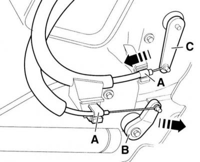
2. Disconnect the tie rod support (A).
3. Disconnect the rods (B) at the heater drive.
4. Remove the footwell nozzle, refer to subsection Removal and installation the footwell nozzle.
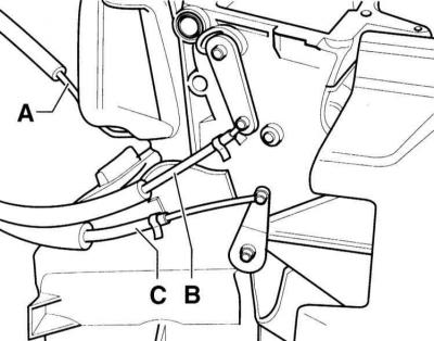
5. Using a screwdriver, pry up and remove the brackets (A) of the heater drive support on the heater housing.
6. Carefully remove the rods from the levers (B) and (C).
Installation
7. Before installation, check the heater rods for ease of movement. If there is any jamming or damage, replace the rods.
Warning: When assembling the heater rod, secure it with clamps and clips so that they do not touch moving parts.
Connecting the cables to the heater control panel
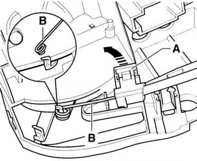
8. Connect the cables (B) so that the winding faces downwards.
9. Connect the green cable (A) of the window/foot area defrost nozzle flap to the heater actuator lever. Secure the support.
10. Connect the yellow cable (B) of the window defrosting nozzle flap to the heater actuator lever. Secure the support.
11. Connect the brown cable (C) of the window defrost nozzle flap to the heater actuator lever. Secure the support.
12. Install the heater actuator.
Connecting the cables to the heater body

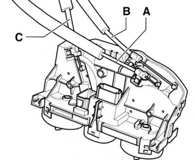
13. Connect the green cable (A) to the window/foot area defroster nozzle flap lever. Do not secure the support yet.
14. Connect the yellow cable (B) to the center throttle lever.
15. Connect the brown cable (C) to the temperature flap lever.
Adjusting the heater rods
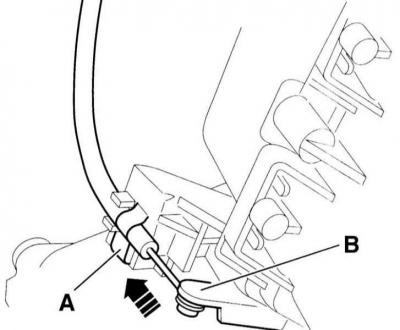
16. Turn the temperature selection knob all the way to the "kalt" ("cold") position.
17. Lightly press the lever (B) on the heater box in the direction of the arrow. In this position, secure the rod to the support with the bracket (A).
18. Turn the air distribution knob all the way to the windshield air distribution position.
19. Lightly press the lever (C) of the central flap in the direction of the arrow, refer to the illustration in point 17. In this position, secure the rod to the support with the bracket (A).
20. Press the glass/foot area defroster flap lever (B) in the direction of the arrow and secure the rod to the support with the bracket (A).
21. Turn both handles in different directions between the extreme stops, they should touch both stops.
22. Remove the footwell nozzle, refer to subsection Removal and installation the footwell nozzle.