
Electrical diagram of heating and air conditioning system
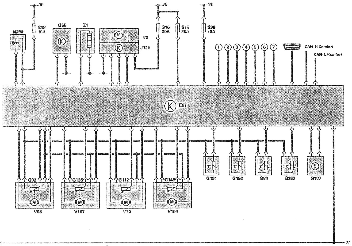
Functional diagram
- E87 — Climate control and indicator panel
- G65 - High pressure sensor
- G89 — Fresh air intake duct temperature sensor
- G92 - Potentiometer in the temperature control flap motor
- G107 - Solar Intensity Photo Sensor
- G112 - Potentiometer in the central flap motor
- G135 - Potentiometer in the defroster flap motor
- G143 - Potentiometer in the recirculation flap motor
- G191 - Temperature sensor on the central deflector
- G192 - Temperature sensor on the footwell vent
- G263 - Evaporator deflector temperature sensor
- J126 — Supply fan control unit
- N₂80 — Air conditioning compressor regulating valve
- S — Fuse
- V2 — Supply fan
- V68 — Temperature control flap motor
- V70 - Central flap motor
- V107 — Defroster flap motor
- V154 — Electric motor for supply ventilation/recirculation flaps
- Z1 — Rear window heating element
- (1) Start-Stop signal from the automatic transmission control unit J217
- (2) Signal "Terminal 31b" from the intermittent windscreen washer/wiper relay J31
- (3) Increase in speed
- (4) ECON signal
- (5) Air conditioning compressor
- (6) Fan speed 1
- (7) Fan speed 2
(The original material is located on the website «AUDIMANUAL.ru»)