Repair Chevrolet Repair Toyota Repair Honda Repair AvtoVAZ Repair Mercedes-Benz Repair BMW Repair Opel
Home  |  Contacts  |  Sitemap  |    
English Русский
Български
Беларускі
Український
Српски
Hrvatski
Română
Polski
Slovenský
Magyar
AudiManual.ru


  • AUDI 80
  • AUDI 100
  • AUDI A3
  • AUDI A4
  • AUDI A6
  • AUDI A8
  • AUDI Q
  • OTHER
  • ARTICLES
C5 Allroad (1999-2005) C5 (1997-2004) C4 (1994-1997)

Electrical diagram of the car heating system (Audi A6 C5)

  • Home
  • Audi A6
  • C5 (1997-2004)
  • Electrical equipment
  • Electrical circuits
  • Electrical diagram of the car heating system
            0
Scheme 24. Heating system of cars with engines ASK, ALG, AGA and ALF

Scheme 24. Heating system of cars with engines ASK, ALG, AGA and ALF
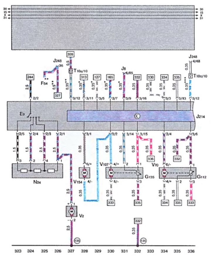
  • E 9 - Fresh air fan switch
  • F 54 - Coolant fan thermal switch
  • G 112 - potentiometer - central flap servomotor
  • G 135 - potentiometer in the servomotor of the blower flap
  • J 8 - parking heater relay
  • J 214 - Thermotronic on-board computer control unit
  • j 248 - control unit of the direct injection device of diesel
  • N 24 - additional resistance of fresh air fan
  • T 10 o - plug connection, 10-pin, brown color, connecting clamp for water tank E-Box
  • V 2 - fresh air fan
  • V 70 - central flap servomotor
  • V 107 - servomotor of the blower flap
  • V 154 - Fresh air/recirculated air flap servomotor
  • 135 - connection to the body ("ground") "2", in the instrument cluster wiring harness

* - cars with parking heating
** - cars with 1.9 l TDI engine
*** - cars with 2.5 l TDI engine
The article was checked by auto expert Alexey Ivanov
This article is available at russian, bulgarian, belarusian, ukrainian, serbian, croatian, romanian, polish, slovak, hungarian

Share information:
Previous articles
Audi A6 C5: Electrical circuits
Next articles

Wiring diagram for radio cabling
Wiring diagram for tail light, brake light, rear turn signals,…
Wiring diagram of fuse holder, siren, cigarette lighter front…
Fuse Holder and Brake Light Switch Wiring Diagram
Electrical diagram of heated rear window, ambient air…
Electrical diagram of battery, starter, three-phase generator,…
Electrical diagram of the Motronic control unit, valve…
Electrical diagram of the Motronic control unit, distribution…


Similar articles on other Audi car models:
Fuel system electrical connections diagram (KE-Jetronic) Audi 80 B3 (1986-1991, petrol)
Pre-heating system Audi 100 C3 (1982-1990, diesel)
Heating, ventilation and air conditioning system Audi A3 Type 8L (1996-2003)
Cooling system — coolant hose connection diagram Audi A4 B8 (2007-2015)
Pre-heating system for diesel engines Audi A8 D2 (1994-2002)
Parts and units of the fuel system (general diagram) Audi Q5 Type 8R (2008-2017)
Electrical diagram of heating and air conditioning system Audi A2 (1999-2005)
Link to this page in different formats


Visitor comments

No comments yet


How much will 11 + 12 =


A6(C5 AR, 1999-2005) 
  • General information
  • User manual
  • Maintenance
  • Troubleshooting
  • Power unit
  • V6 petrol engines
  • V8 petrol engines
  • Diesel engines
  • Cooling and heating system
  • Injection system (gasoline)
  • Fuel system (diesel)
  • Supply system
  • Exhaust system
  • Ignition system
  • Transmission
  • Clutch
  • Mechanical gearbox
  • Automatic gearbox
  • Chassis
  • Brake system
  • Car suspension
  • Steering
  • Body
  • Body elements
  • Doors, locks and windows
  • Electrical equipment
  • Equipment and devices
  • Power devices
  • Electrical circuits
  • Schemes (petrol engine 2.7 l)
  • Schemes (petrol engine 4.2 l)
  • Schemes (diesel engine 2.5 l)
 
A6(C5, 1997-2004) 
  • General information
  • User manual
  • Maintenance
  • Power unit
  • Engine repair
  • Cooling system
  • Fuel system
  • Engine management
  • Fuel system (diesel)
  • Exhaust system
  • Transmission
  • Clutch
  • Car gearbox
  • Chassis
  • Front suspension
  • Rear suspension
  • Steering
  • Wheels and tires
  • Brake system
  • Body
  • Exterior
  • Interior
  • Electrical equipment
  • Air conditioner
  • Equipment and devices
  • Electrical circuits
 
A6(C4, 1994-1997) 
  • General information
  • User manual
  • Maintenance (gasoline)
  • Maintenance (Diesel)
  • Gasoline engines
  • 4 cylinder engines
  • 5 cylinder engines
  • 6 cylinder engines
  • Diesel engines
  • 4 cylinder engines
  • 5 cylinder engines
  • Engine repair
  • Removal and reassembly
  • Cooling system
  • Single point injection system
  • Multipoint injection system
  • MPI/MPFI injection system
  • Fuel system (diesel)
  • Exhaust system
  • Ignition system
  • Transmission
  • Clutch
  • Manual transmission
  • Automatic transmission
  • Drive shafts
  • Chassis
  • Brake system
  • Front suspension
  • Rear suspension
  • Steering
  • Body
  • Exterior (external elements)
  • Interior (internal elements)
  • Electrical equipment
  • Power devices
  • Lighting and appliances
  • Electrical circuits
 
AudiManual.ru © 2017-2026 · Mobile version · Feedback · Sitemap: EN BG BY UA RS HR RO PL SK HU · Site search · News and articles
80 B2 · 80 B3 petrol · 80 B3 · 80 B4 · 100 C3 diesel · 100 C3 petrol · 100 C3 · 100 C4 petrol · 100 C4 · A3 Type 8L · A4 B5 petrol · A4 B5 · A4 B6 petrol · A4 B6 · A4 B7 · A4 B8 · A6 C4 · A6 C5 · A6 C5 Allroad · A8 D2 · Q5 Type 8R · Q7 Typ 4L · Audi A2 ·
This site uses cookies 🍪. Click the button to accept this fact.