Repair Chevrolet Repair Toyota Repair Honda Repair AvtoVAZ Repair Mercedes-Benz Repair BMW Repair Opel
Home  |  Contacts  |  Sitemap  |    
English Русский
Български
Беларускі
Український
Српски
Hrvatski
Română
Polski
Slovenský
Magyar
AudiManual.ru


  • AUDI 80
  • AUDI 100
  • AUDI A3
  • AUDI A4
  • AUDI A6
  • AUDI A8
  • AUDI Q
  • OTHER
  • ARTICLES
C5 Allroad (1999-2005) C5 (1997-2004) C4 (1994-1997)

Fuse Holder and Brake Light Switch Wiring Diagram (Audi A6 C5)

  • Home
  • Audi A6
  • C5 (1997-2004)
  • Electrical equipment
  • Electrical circuits
  • Fuse Holder and Brake Light Switch Wiring Diagram
            0
Scheme 20. Fuse holder, brake light switch for cars with ASK, ALG, AGA and ALF engines

Scheme 20. Fuse holder, brake light switch for cars with ASK, ALG, AGA and ALF engines
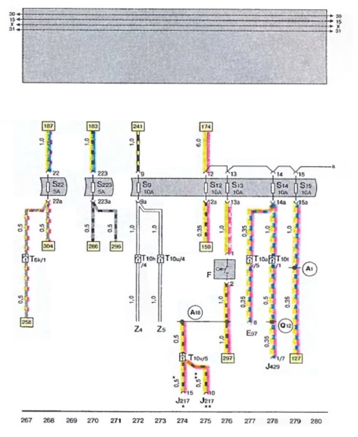
  • E 97 - Memory control device
  • F - brake light switch
  • J 127 - Automatic transmission control unit
  • J 429 - Central locking control unit
  • S 9 - fuse in holder
  • S 12 - fuse in holder
  • S 13 - fuse in holder
  • S 14 - fuse in holder
  • S 15 - fuse in holder
  • S 22 - fuse in holder
  • S 223 - fuse in holder
  • T 6 k - plug connection, 6-pin, color pink, connecting clamp of pillar A, right
  • T 10 h - plug connection, 10-pin, black, connecting clamp pillar A, left
  • T 10 t - plug connection, 10-pin, orange, connecting clamp pillar A, right
  • T 10 u - plug connection, 10-pin, black, connecting clamp pillar A, right
  • T 10 v - plug connection, 10-pin, brown, connecting clamp pillar A, right
  • T 15a - plug connection, 15-pin, black, connecting clamp pillar A, left
  • Z 4 - heated rearview mirror (driver side)
  • Z 5 - heated rearview mirror (passenger side)
  • A 1 - positive connection (30A), in the instrument cluster wiring harness
  • A 18 - connection (54), in the instrument cluster wiring harness
  • 012 - positive connection (30A), in the wiring harness of the window lifter / central lock and door contact switch

*- cars with automatic transmission 01N
** - cars with automatic transmission 01V

The original version is on the portal: AUDIMANUAL
The article was checked by auto expert Alexey Ivanov
This article is available at russian, bulgarian, belarusian, ukrainian, serbian, croatian, romanian, polish, slovak, hungarian

Share information:
Previous articles
Audi A6 C5: Electrical circuits
Next articles

Electrical diagram of the fuse holder, headlights of cars
Wiring diagram for fuse holder, license plate lamp, glove box…
Electrical diagram of windshield washer and wiper, heated…
Warning Light Switch Wiring Diagram
Wiring diagram of fuse holder, siren, cigarette lighter front…
Wiring diagram for tail light, brake light, rear turn signals,…
Wiring diagram for radio cabling
Electrical diagram of the car heating system


Similar articles on other Audi car models:
Wiring diagram of the light switch, headlight switch and light… Audi 80 B4 (1991-1996)
Fuse box brake light switch Audi 100 C4 (1990-1994, petrol)
Removal, installation and adjusting the brake light switch Audi A3 Type 8L (1996-2003)
Removal and installation the brake light switch Audi A4 B6 (2000-2006)
High-mounted brake light Audi A8 D2 (1994-2002)
Comfort system control unit, brake light interlock and D/W… Audi Q7 Typ 4L (2005-2015, diesel)
Removal the cup holder and hazard warning light switch Audi A2 (1999-2005)
Link to this page in different formats


Visitor comments

No comments yet


How much will 42 + 30 =


A6(C5 AR, 1999-2005) 
  • General information
  • User manual
  • Maintenance
  • Troubleshooting
  • Power unit
  • V6 petrol engines
  • V8 petrol engines
  • Diesel engines
  • Cooling and heating system
  • Injection system (gasoline)
  • Fuel system (diesel)
  • Supply system
  • Exhaust system
  • Ignition system
  • Transmission
  • Clutch
  • Mechanical gearbox
  • Automatic gearbox
  • Chassis
  • Brake system
  • Car suspension
  • Steering
  • Body
  • Body elements
  • Doors, locks and windows
  • Electrical equipment
  • Equipment and devices
  • Power devices
  • Electrical circuits
  • Schemes (petrol engine 2.7 l)
  • Schemes (petrol engine 4.2 l)
  • Schemes (diesel engine 2.5 l)
 
A6(C5, 1997-2004) 
  • General information
  • User manual
  • Maintenance
  • Power unit
  • Engine repair
  • Cooling system
  • Fuel system
  • Engine management
  • Fuel system (diesel)
  • Exhaust system
  • Transmission
  • Clutch
  • Car gearbox
  • Chassis
  • Front suspension
  • Rear suspension
  • Steering
  • Wheels and tires
  • Brake system
  • Body
  • Exterior
  • Interior
  • Electrical equipment
  • Air conditioner
  • Equipment and devices
  • Electrical circuits
 
A6(C4, 1994-1997) 
  • General information
  • User manual
  • Maintenance (gasoline)
  • Maintenance (Diesel)
  • Gasoline engines
  • 4 cylinder engines
  • 5 cylinder engines
  • 6 cylinder engines
  • Diesel engines
  • 4 cylinder engines
  • 5 cylinder engines
  • Engine repair
  • Removal and reassembly
  • Cooling system
  • Single point injection system
  • Multipoint injection system
  • MPI/MPFI injection system
  • Fuel system (diesel)
  • Exhaust system
  • Ignition system
  • Transmission
  • Clutch
  • Manual transmission
  • Automatic transmission
  • Drive shafts
  • Chassis
  • Brake system
  • Front suspension
  • Rear suspension
  • Steering
  • Body
  • Exterior (external elements)
  • Interior (internal elements)
  • Electrical equipment
  • Power devices
  • Lighting and appliances
  • Electrical circuits
 
AudiManual.ru © 2017-2026 · Mobile version · Feedback · Sitemap: EN BG BY UA RS HR RO PL SK HU · Site search · News and articles
80 B2 · 80 B3 petrol · 80 B3 · 80 B4 · 100 C3 diesel · 100 C3 petrol · 100 C3 · 100 C4 petrol · 100 C4 · A3 Type 8L · A4 B5 petrol · A4 B5 · A4 B6 petrol · A4 B6 · A4 B7 · A4 B8 · A6 C4 · A6 C5 · A6 C5 Allroad · A8 D2 · Q5 Type 8R · Q7 Typ 4L · Audi A2 ·
This site uses cookies 🍪. Click the button to accept this fact.