Repair Chevrolet Repair Toyota Repair Honda Repair AvtoVAZ Repair Mercedes-Benz Repair BMW Repair Opel
Home  |  Contacts  |  Sitemap  |    
English Русский
Български
Беларускі
Український
Српски
Hrvatski
Română
Polski
Slovenský
Magyar
AudiManual.ru


  • AUDI 80
  • AUDI 100
  • AUDI A3
  • AUDI A4
  • AUDI A6
  • AUDI A8
  • AUDI Q
  • OTHER
  • ARTICLES
C5 Allroad (1999-2005) C5 (1997-2004) C4 (1994-1997)

Electrical diagram of the fuse holder, headlights of cars (Audi A6 C5)

  • Home
  • Audi A6
  • C5 (1997-2004)
  • Electrical equipment
  • Electrical circuits
  • Electrical diagram of the fuse holder, headlights of cars
            0
Scheme 19. Fuse holder, headlights of cars with ASK, ALG, AGA and ALF engines

Scheme 19. Fuse holder, headlights of cars with ASK, ALG, AGA and ALF engines
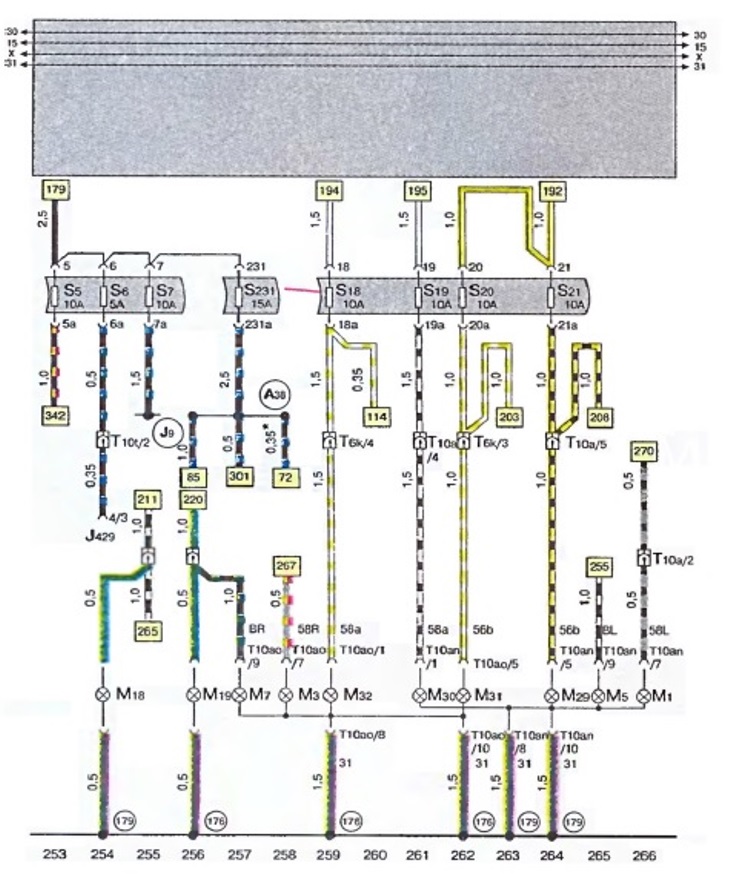
  • J 429 - Central locking control unit
  • M 1 - left parking light
  • M3 - parking light lamp on the right
  • M 5 - left turn signal lamp
  • M 7 - right turn signal lamp
  • M 18 - left side turn signal lamp
  • M 19 - Right side turn signal lamp
  • M 29 - low beam headlight bulb, left
  • M 30 - high beam headlight bulb, left
  • M 31 - low beam headlight bulb, right
  • M 32 - high beam headlight bulb, right
  • S 5 - fuse in holder
  • S 6 - fuse in holder
  • S 7 - fuse in holder
  • S 18 - fuse in holder
  • S 19 - fuse in holder
  • S 20 - fuse in holder
  • S 21 - fuse in holder
  • S 231 - fuse in holder
  • T 6 k - plug connection, 6-pin, color pink, connecting clamp pillar A, right
  • T 10 a - plug connection, 10-pin, color pink, connecting clamp of pillar A, left
  • T 101 - plug connection, 10-pin, orange, connecting clamp pillar A, right
  • T 10 an - plug connection, 10-pin, on the left headlight
  • T 10 ao - plug connection, 10-pin, on the headlight on the right
  • 176 - connection to the housing ("ground"), in the wiring harness of the headlight on the right
  • 179 - connection to the housing ("ground"), in the left headlight wiring harness
  • A 38 - connection plus "2" (15a), in the instrument cluster wiring harness
  • J 9 - connection plus "1" (15a), in the ABS wiring harness

* - front-wheel drive cars
The article was checked by auto expert Alexey Ivanov
This article is available at russian, bulgarian, belarusian, ukrainian, serbian, croatian, romanian, polish, slovak, hungarian

Share information:
Previous articles
Audi A6 C5: Electrical circuits
Next articles

Wiring diagram for fuse holder, license plate lamp, glove box…
Electrical diagram of windshield washer and wiper, heated…
Warning Light Switch Wiring Diagram
Electrical diagram of the light switch regulator and instrument…
Fuse Holder and Brake Light Switch Wiring Diagram
Wiring diagram of fuse holder, siren, cigarette lighter front…
Wiring diagram for tail light, brake light, rear turn signals,…
Wiring diagram for radio cabling


Similar articles on other Audi car models:
Electrical connection diagram for headlights, taillights and… Audi 80 B3 (1986-1991, petrol)
Electrical equipment diagram of AUDI «100» cars with carburetor… Audi 100 C3 (1982-1990, petrol)
Audi A3/S3 cars — summary Audi A3 Type 8L (1996-2003)
Operating instructions for quattro cars Audi A4 B5 (1994-2001, petrol)
Checking the electrical wiring Audi A8 D2 (1994-2002)
Electrical test of fuel pre-supply pump «G6» Audi Q5 Type 8R (2008-2017)
Electrical diagram of the 1.4 liter petrol engine BBY Audi A2 (1999-2005)
Link to this page in different formats


Visitor comments

No comments yet


How much will 16 + 47 =


A6(C5 AR, 1999-2005) 
  • General information
  • User manual
  • Maintenance
  • Troubleshooting
  • Power unit
  • V6 petrol engines
  • V8 petrol engines
  • Diesel engines
  • Cooling and heating system
  • Injection system (gasoline)
  • Fuel system (diesel)
  • Supply system
  • Exhaust system
  • Ignition system
  • Transmission
  • Clutch
  • Mechanical gearbox
  • Automatic gearbox
  • Chassis
  • Brake system
  • Car suspension
  • Steering
  • Body
  • Body elements
  • Doors, locks and windows
  • Electrical equipment
  • Equipment and devices
  • Power devices
  • Electrical circuits
  • Schemes (petrol engine 2.7 l)
  • Schemes (petrol engine 4.2 l)
  • Schemes (diesel engine 2.5 l)
 
A6(C5, 1997-2004) 
  • General information
  • User manual
  • Maintenance
  • Power unit
  • Engine repair
  • Cooling system
  • Fuel system
  • Engine management
  • Fuel system (diesel)
  • Exhaust system
  • Transmission
  • Clutch
  • Car gearbox
  • Chassis
  • Front suspension
  • Rear suspension
  • Steering
  • Wheels and tires
  • Brake system
  • Body
  • Exterior
  • Interior
  • Electrical equipment
  • Air conditioner
  • Equipment and devices
  • Electrical circuits
 
A6(C4, 1994-1997) 
  • General information
  • User manual
  • Maintenance (gasoline)
  • Maintenance (Diesel)
  • Gasoline engines
  • 4 cylinder engines
  • 5 cylinder engines
  • 6 cylinder engines
  • Diesel engines
  • 4 cylinder engines
  • 5 cylinder engines
  • Engine repair
  • Removal and reassembly
  • Cooling system
  • Single point injection system
  • Multipoint injection system
  • MPI/MPFI injection system
  • Fuel system (diesel)
  • Exhaust system
  • Ignition system
  • Transmission
  • Clutch
  • Manual transmission
  • Automatic transmission
  • Drive shafts
  • Chassis
  • Brake system
  • Front suspension
  • Rear suspension
  • Steering
  • Body
  • Exterior (external elements)
  • Interior (internal elements)
  • Electrical equipment
  • Power devices
  • Lighting and appliances
  • Electrical circuits
 
AudiManual.ru © 2017-2026 · Mobile version · Feedback · Sitemap: EN BG BY UA RS HR RO PL SK HU · Site search · News and articles
80 B2 · 80 B3 petrol · 80 B3 · 80 B4 · 100 C3 diesel · 100 C3 petrol · 100 C3 · 100 C4 petrol · 100 C4 · A3 Type 8L · A4 B5 petrol · A4 B5 · A4 B6 petrol · A4 B6 · A4 B7 · A4 B8 · A6 C4 · A6 C5 · A6 C5 Allroad · A8 D2 · Q5 Type 8R · Q7 Typ 4L · Audi A2 ·
This site uses cookies 🍪. Click the button to accept this fact.