



Table of contents: Removal ↓ Installation ↓
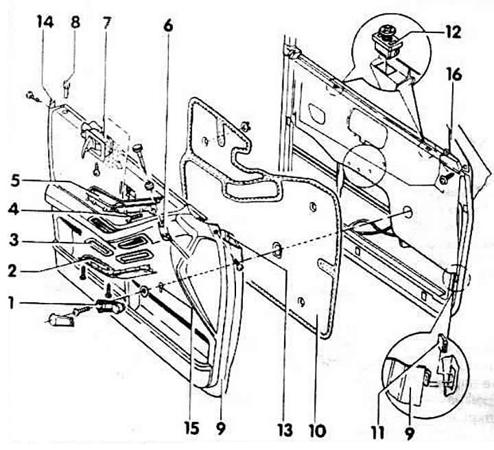
1 - window opening handle
Lubricate the screw with a locking agent, for example VAG AMW 197 OOO 001.
2 - lower part of the armrest
When installing, the latch protrusion must fit into the cutout of the upper part
3 - gasket
4 - Phillips head screws
5 - upper part of the armrest
6 - mirror installation
7 - door opening handle from the inside
8 - opening lock button
9 - sheathing
10 - sound-absorbing gasket
Attached to the trim with brackets. May not be removed when removing the trim.
11 - pads for hooks
They are inserted into the door holes, but can be glued to facilitate installation.
12 - plastic insert
For height adjustment when installing new trim.
13 - front transition element
Partially glued to the frame, carefully separate and remove. Glue: VAG D001300
14 - rear transition element
Partially glued to the frame, carefully separate and remove. Glue: VAG D001300.
15 - gasket
For window opening handle.
16 - overlay
It is not removed when the trim is removed.
Removal
Use a small screwdriver to pry up and remove the mirror installation handle. Remove the outer installation disc.
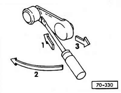
Remove the window opening handle. To do this, as shown in the figure, insert a small screwdriver between the handle and the trim "1", and the trim will snap off. Pull the trim "3" back. If necessary, turn the handle in the direction of the arrow "2".
While holding the lever, unscrew the Phillips screw of the window handle. Remove the screw with the washer and pull the lever off the window lifter shaft.
Remove the plastic trim from the window regulator shaft.
Remove the Phillips head screw on the front and back sides.
Remove the 2 screws on the bottom of the armrest, pull it down from the back and pull it out backwards.
Unscrew the 4 screws on the top of the armrest and remove them with the washers.
First pull the upper part of the armrest slightly upwards from the front. Remove the mirror mounting element downwards, for which lift the two polymer hooks, remove the armrest.
Remove the door opening unit from the inside. To do this, set the handle to the open position, which will make the mounting screw hole visible. Unscrew the screw and continue holding the handle in the open position. Slightly moving the handle cover forward, pull it outward. At the same time, press the edge of the cover through the armrest ledge with a small screwdriver and remove the door opening unit
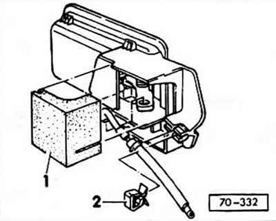
Remove seal -1-.
Remove the spring clip "2". Pull the cable out of the holder and disconnect.
Carefully separate the glued front and rear transition elements and remove.
Remove the door handle by pressing it.
Pull the door trim up hard or hit the trim hard with your fists from below. This will release the trim from the hooks and allow it to be lifted upward.
Remove the rubber pads under the hooks from the door holes.
Remove the flat bracket at the top of the door plate.
Installation
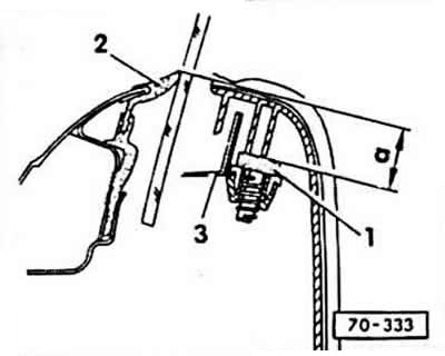
Insert the door trim with hooks into the holes provided for this purpose in the door and check the installation. The door trim must be at the same level with the outer trim "2" of the door shaft. Otherwise, accordingly turn the adjusting screw "1" in the bracket "3", the basic dimension is a = 21 mm.
Insert rubber pads for hooks into the holes in the door; if necessary, you can glue them.
Press the flat bracket into the top of the door plate.
Insert the door trim with hooks into the holes provided for this purpose in the door, press and at the same time press down hard. At the same time, maintain the correct fit of the seal "1" of the window lifter handle and insert the door button into the hole in the trim. Hit the trim with your fists from above until the hooks snap into place.
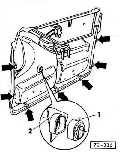
Insert and glue the front and rear transition pieces.
Install the window lift handle. First insert the cover into the hole in the trim, then place the handle on the axle and tighten the screws. When the window is closed, the handle should be facing upwards forward at an angle of 40. First, lubricate the fastening screws with a readily soluble locking agent.
Place the cover on the window lifter handle lever from behind and snap it into place.
Install the door opening unit from the inside. To do this, connect the cable to the eye of the unit, insert it into the holder and secure it with a spring clip. Insert the rectangular cover so that the inside of the door handle is completely covered. Move the handle trim back and simultaneously press it into the door trim. Set the handle to the open position and tighten the fastening screw. To do this, either use a magnetic screwdriver or insert the screw into the hole in the handle trim before installation.
Insert the upper part of the armrest from the back side, snap the mirror installation unit into the armrest from below.
Tighten the 4 screws securing the upper part of the armrest.
Insert the lower part of the armrest from the front and press down from the back. Tighten the screws.
On the front side, tighten one Phillips head screw at the front and one at the back
Insert the outer mirror adjustment disc, snap the height adjustment handle. If necessary, adjust the mirror installation first.
(A link to the original source is available on the website: AudiManual.ru)