
Table of contents: Front side light ↓ Front direction indicators (80 model) ↓ Front direction indicators (models… ↓ Front fog light (80 model) ↓ Front fog light (models 90 and Coupe) ↓ Rear Lamp Block - Trunk Lid (Sedan) ↓ Rear Light Assembly - Rear Wing… ↓ Rear lamp unit (Coupe) ↓ License plate light ↓ Interior lighting ↓ Trunk light lamp ↓ Engine bay light ↓ Map reading lamp (coupe models) ↓ Side indication lamps ↓ Glove compartment light ↓ Illumination of switches on the… ↓ Instrument panel lighting ↓ Heater control panel lighting ↓
Note: Incandescent lamps must always be replaced with identical type and specifications as given in Specifications.
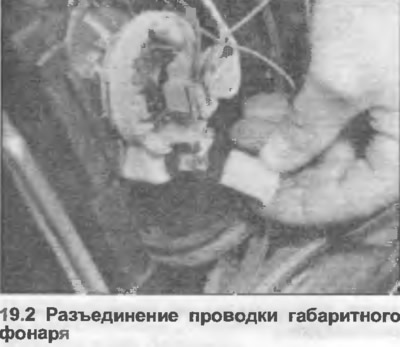
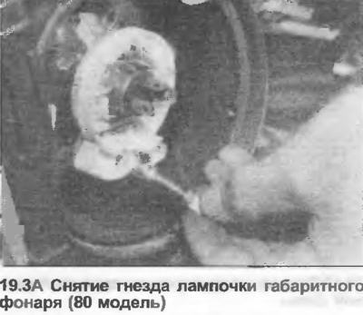
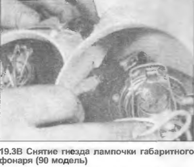
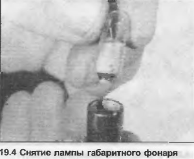
Front side light
1. Remove the plastic cover on the back of the headlight (refer to Chapter 17, if necessary).
2. Disconnect the wiring (where it is equipped) (photo).
3. Remove the bulb socket from the reflector (photo).
4. To remove, press and turn the bulb.
5. Installation is carried out in reverse order.
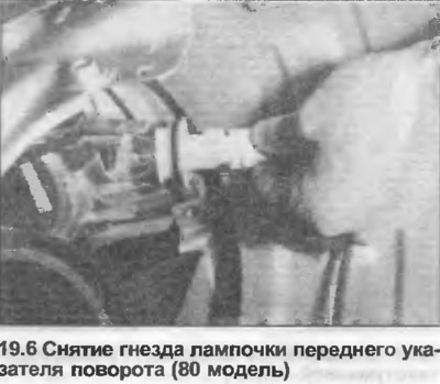
Front direction indicators (80 model)
6. Turn the bulb socket on the back of the lamp counterclockwise and remove it (photo).
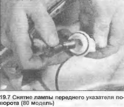
7. To remove, press and turn the bulb (photo).
8. Installation is carried out in reverse order.
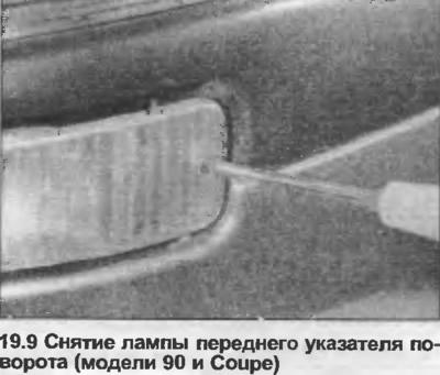
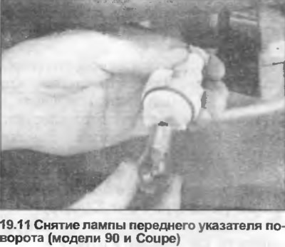
Front direction indicators (models 90 and Coupe)
9. Unscrew the screw and remove the front turn signal lamp (photo).
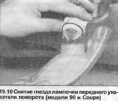
10. Turn the bulb socket counterclockwise and remove it together with the bulb (photo).
11. To remove, press and turn the bulb (photo).
12. Installation is carried out in reverse order.
Front fog light (80 model)
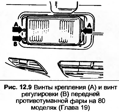
13. Use a screwdriver to remove the plastic frame.
14. Unscrew the screws and remove the fog light.
15. Disconnect the wire, then disconnect the spring clip and remove the bulb.
16. Reassemble in reverse order, make sure that the tabs on the lamp fit correctly into the reflector, and finally adjust the lamp. The procedure is the same as described in Chapter 18.
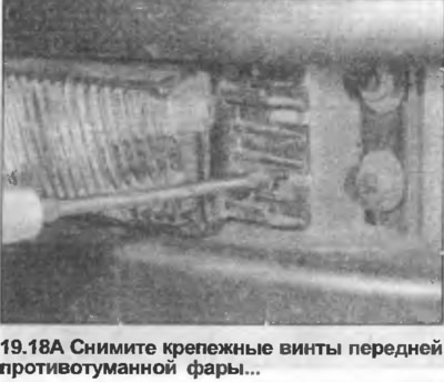
Front fog light (models 90 and Coupe)
17. Remove the front turn signal bulb as described in step 9.
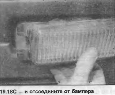
18. Unscrew the two mounting screws, pull out the lamp and detach it from the bumper (photo).
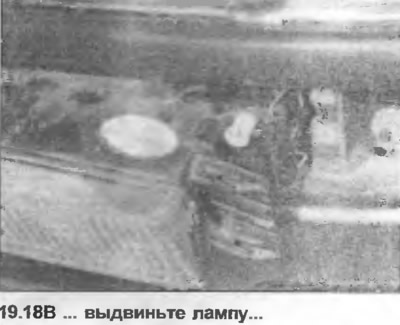
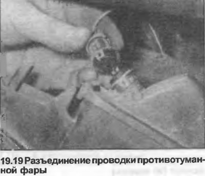
19. Disconnect the wiring (photo).
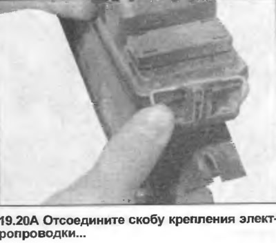
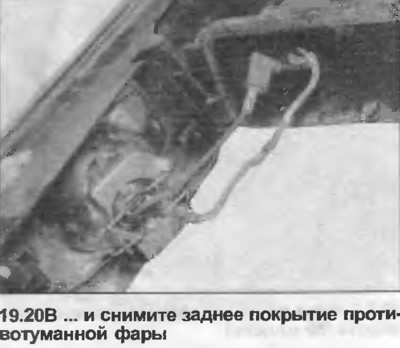
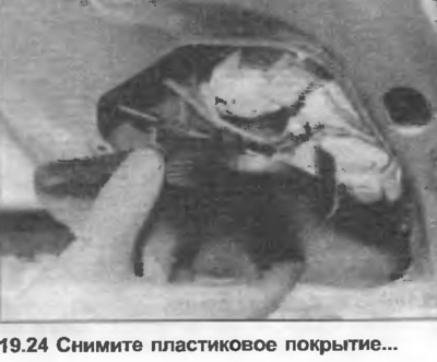
20. Disconnect the wiring bracket and remove the cover from the back of the lamp (photo).
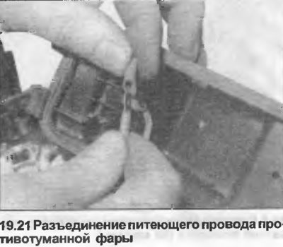
21. Disconnect the wiring to the incandescent lamp (photo).
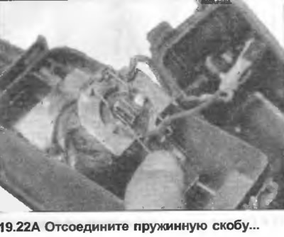
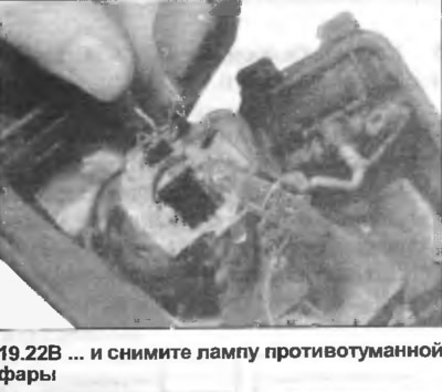
22. Disconnect the spring clip, remove the incandescent lamp from the reflector (photo).
23. Installation is carried out in the reverse order, make sure that the incandescent lamp is correctly inserted into the reflector.
Rear Lamp Block - Trunk Lid (Sedan)
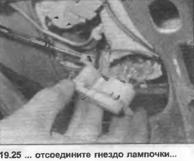
24. Open the trunk lid, remove the plastic covering (photo).
25. Turn the corresponding bulb socket counterclockwise and remove it together with the bulb (photo).
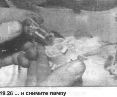
26. Press, turn and remove the lamp (photo).
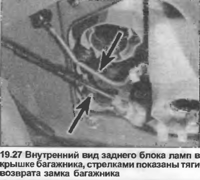
27. If necessary, the lamp can be removed by unscrewing the fastening nut. On the right side, it is also necessary to disconnect the trunk lock return rods (photo).
28. Installation is carried out in reverse order.
Rear Light Assembly - Rear Wing (Sedan)
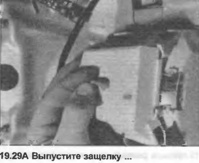
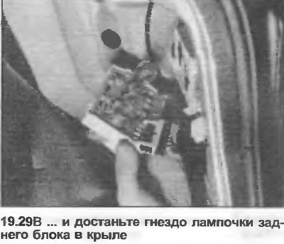
29. Open the trunk lid, then release the latch and remove the bulb socket (photo).
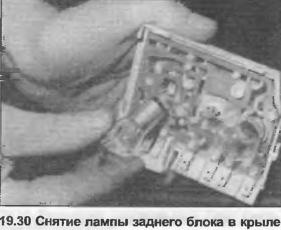
30. Press, turn and remove the incandescent bulb (photo).
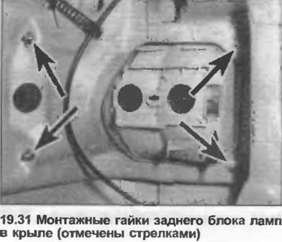
31. If necessary, the lamp can be removed by unscrewing the nuts (photo).
32. Installation is carried out in reverse order.
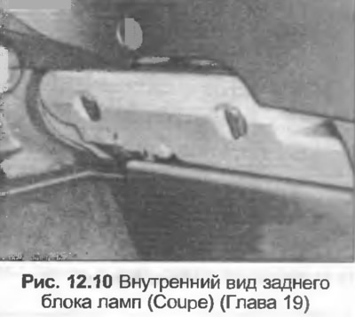
Rear lamp unit (Coupe)
33. Open the trunk lid, then release the latch and remove the bulb socket.
34. Press, turn and remove the bulb.
35. Installation is carried out in reverse order
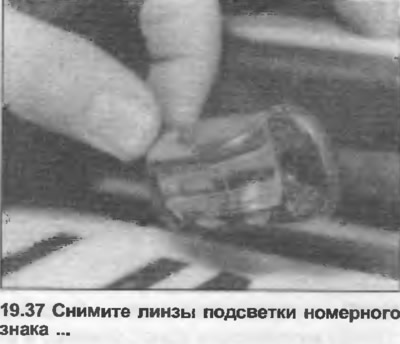
License plate light
36. Open the trunk lid or rear door.
37. Unscrew the screws, remove the lens, noting its orientation (photo).
38. Press, turn and remove the incandescent lamp (photo).
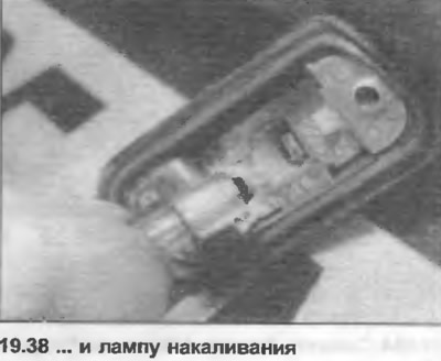
39. Installation is carried out in the reverse order, make sure that the rubber seal under the lens is correctly positioned and the protrusion on the lens fits into its place in the lamp housing.
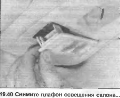
Interior lighting
40. Using a small screwdriver, remove the interior light from the ceiling (photo).
41. Remove the incandescent lamp from the spring contacts (photo).
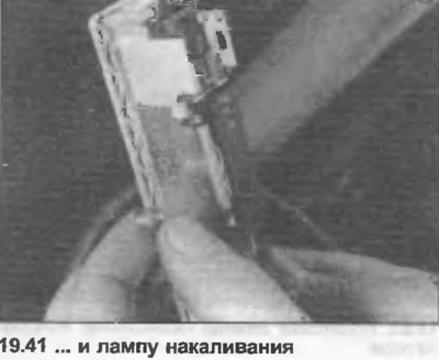
42. Installation is carried out in the reverse order, making sure that the spring contacts are sufficiently taut to hold the incandescent lamp firmly.
Trunk light lamp
43. Use a screwdriver to remove the lens (photo).
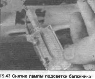
44. Remove the incandescent lamp from the spring contacts.
45. Installation is carried out in the reverse order, making sure that the spring contacts are sufficiently taut to hold the incandescent lamp firmly.
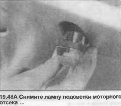
Engine bay light
46. Press the sides of the lampshade together and remove it.
47. Press, turn and remove the bulb.
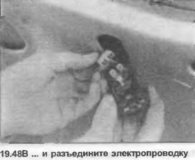
48. If necessary, remove the cartridge from the hood and disconnect the electrical wiring (photo).
49. Installation is carried out in reverse order.
Map reading lamp (coupe models)
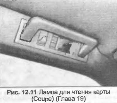
50. Fix the grip down and unscrew the screws.
51. Remove the handle and lamp assembly and disconnect the wiring.
52. Remove the incandescent lamp from the spring contacts.
53. Installation is carried out in the reverse order, making sure that the spring contacts are sufficiently taut to hold the incandescent lamp firmly.
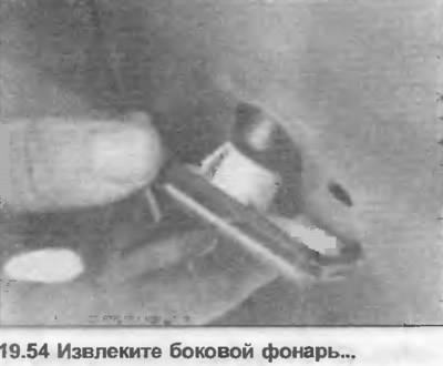
Side indication lamps
54. Push the light back and remove it from the hole (photo).
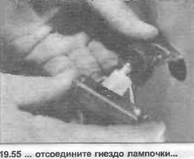
55. Remove the bulb socket from the back of the light (photo).
56. Remove the lamp from the socket (photo).
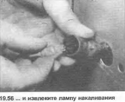
57. Installation is carried out in reverse order.
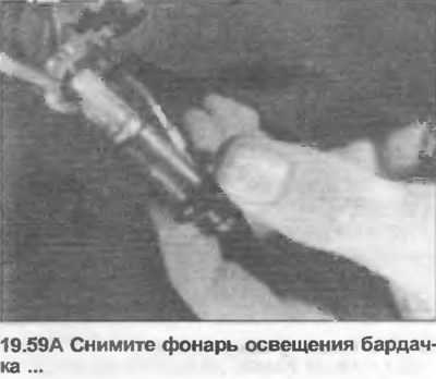
Glove compartment light
58. Remove the glove compartment as described in Section 11.
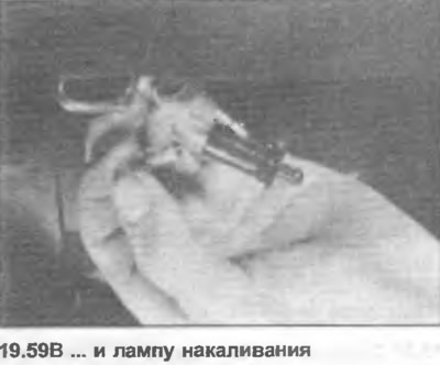
59. Remove the switch/bulb socket from the housing, then press, twist and remove the bulb (photo).
60. Installation is carried out in reverse order.
Illumination of switches on the dashboard
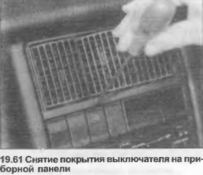
61. Remove the cover from the switch using a screwdriver (photo).
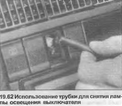
62. Remove the incandescent bulb using a piece of plastic or rubber tubing that fits tightly over the bulb (photo).
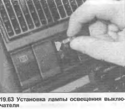
63. Insert the new lamp into place, install the cover (photo).
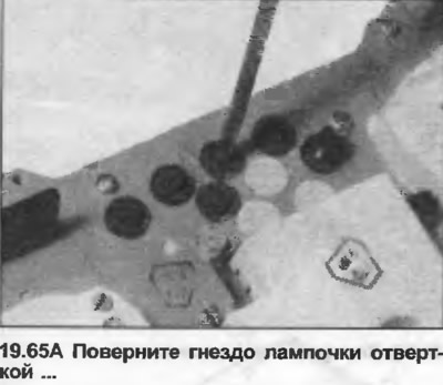
Instrument panel lighting
64. Remove the instrument panel as described in Chapter 15.
65. Turn the bulb socket with a screwdriver until the tabs come out of the holes in the circuit board. Remove the bulb socket and, where equipped, slide out the bulb (photo).
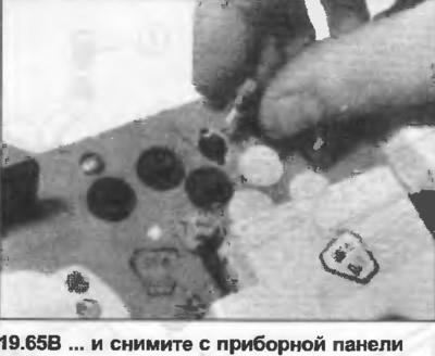
66. Installation is carried out in reverse order.
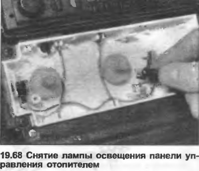
Heater control panel lighting
67. Remove the heater control knobs and panel frame as described in Section 11, Chapter 30.
68. Remove the bulb socket from the mounting bracket, then push, twist and remove the bulb (photo).
69. Installation is carried out in reverse order.
(The original text of the material can be found on the website AudiManual.ru)