
Withdrawal
Carefully! Risk of damage to electronic components when disconnecting the battery. Carefully follow the process of removing the battery.
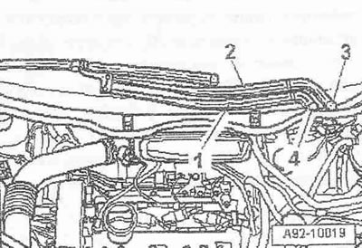
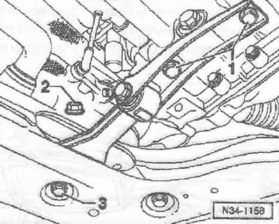
Disconnect ground cable from battery. Wash the outside of the hood and cover it with a protective cover. Unlock the service cover from the inside. Unlock bonnet -arrows- and pull it slightly forward. Pull on protective boot -VAS 6011- on bonnet. Remove bonnet and place on protective cover -VAS 6011-. Loosen protective caps -3- and -4- for wiper arms using a screwdriver. Loosen the nuts on both wiper arms a few turns. Detach wiper arms -1- and -2- one after the other, tilting slightly off axis. Completely unscrew nuts and remove wiper arms.
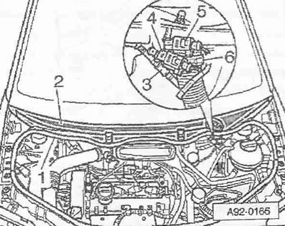
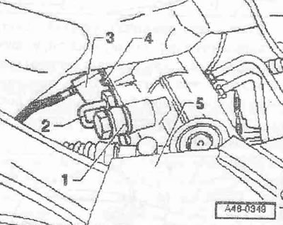
Disconnect windshield washer line -3-. Unplug electrical connectors -4- and -5- for heated windshield washer jets, if fitted. Loosen hose clamp -6- using special pliers -VAG 1921- and detach coolant drain line from cowling grille. Remove rubber seal -1- for fairing grille. Remove fairing grille -2-. Release the windshield washer line.
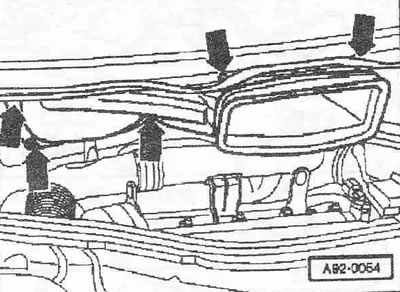
Remove nuts and bolts -arrows-. Remove the air duct towards the front and unscrew it towards the right side of the vehicle.
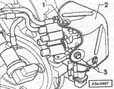
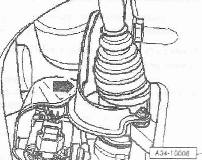
Remove engine cover -arrows-. Remove the noise-insulating lining installed under it by removing the hose of the crankcase ventilation system for this. Remove the hydraulic control unit. Unscrew bolt -1- on top of heat shield -2- of gear selector unit.
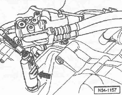
Disconnect electrical connector -arrow- from vehicle speed sender -G68-.
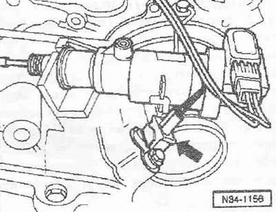
Unplug electrical connector -arrow- for gearbox speed sender -G38-.
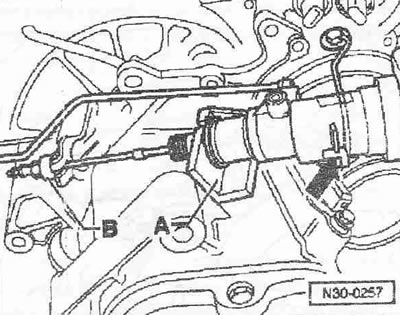
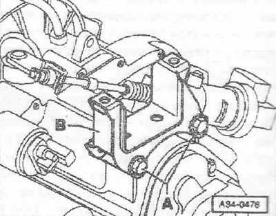
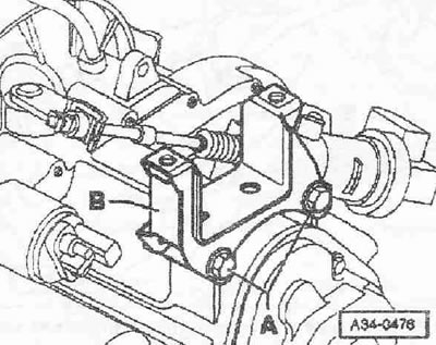
Loosen lock nut -B- and adjusting nut on clutch rod. Hang the clutch rod on the drive lever.
Instruction. It is forbidden to open the hydraulic line of the clutch slave cylinder.
Hang the wire clip in the place marked by -arrow- and remove the clutch slave cylinder from the stop -A-. Set the clutch slave cylinder aside, do not open the line system. Loosen the wire clamp securing the gearbox. Unscrew all other brackets and gearbox lines.
Remove front wheels. Remove soundproofing. Unscrew the heat shield on the right drive shaft. Remove the left and right drive shafts.
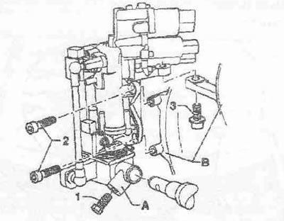
Cut wire retainer -2- and remove cover -3- of solenoid switch -1- upwards.
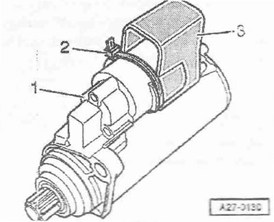
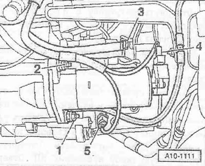
Remove nut -2-. Disconnect wires -3- from starter solenoid switch. Detach the wire bracket. Remove the top starter bolt. Remove nut -1- and remove lower starter ground wire. Disconnect plug connector from terminal 50 -pos. 4- on the electromagnetic switch. Unscrew the lower double bolt, remove the starter downwards. Unplug electrical connector -5- from reversing light switch -F4- and move out
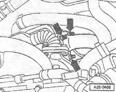
Unscrew front catalytic converter -arrows- and secure to front wall of body.
Remove bolts -3- and remove heat shield -2- of gear selector unit.
Instruction. Do not open the shifter hydraulic lines.
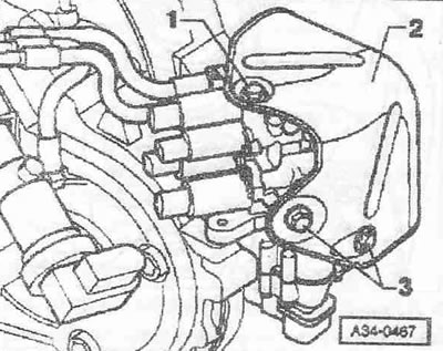
Loosen bolt -1- a few turns. Remove the gearshift pin -A- from the gearshift shaft. Unscrew bolts -2- and -3-. Fasten the gear selector as high as possible on the body.
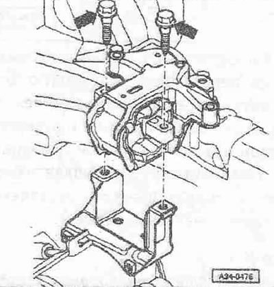
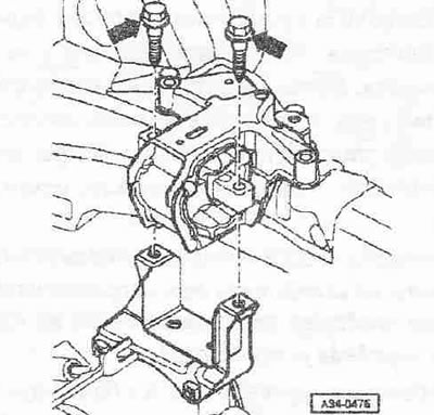
Unscrew bolts -1, 3- and nut -2- and remove the bottom support of the power unit.
Vehicles with power steering: Detach hydraulic lines -1- and 2- from steering box.
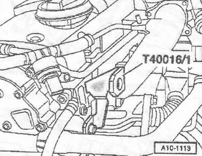
Unscrew both upper bolts securing the engine to the gearbox. Screw rear left transport strip -T40016/1- to cylinder head.
Fit adapter -10.222 A/3- onto cross member -10.222 A-. Position crosshead -10.222 A- with adapter -10.222 A/13- on wing connecting edge. Attach adapters. -10.222 A/13- at the rear on the bonnet retaining hook -arrow-.
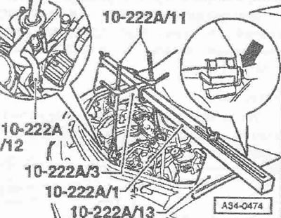
Apply a slight pre-tension to the power unit using the lead screws. Unscrew bolts -arrows- for left gearbox support. Carefully move the power unit into an inclined position by unscrewing the left-hand spindle of the traverse -10.222 A- downwards.
Release screws -A- and remove gearbox console -B-.
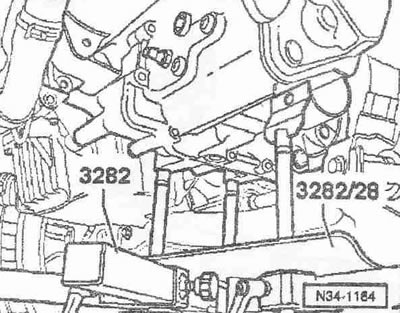
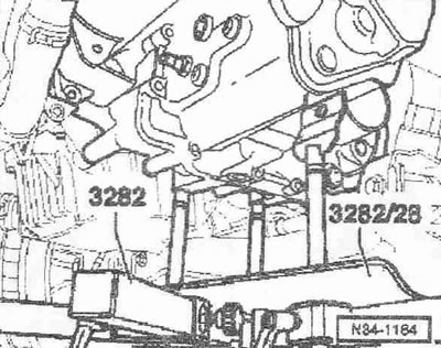
Equip bracket -3282- for removing gearbox "085 DS" adjustment plate -3282/28-. Position gearbox support -3282- on power unit jack -VAG 1383 A-. Orient the levers of the fastening device according to the holes in the mounting template. Screw on fastener -A- as shown on adjusting plate. Screw pins -3282/29- instead of fastener -C-. Put the power unit lift under the vehicle. The arrow -B- on the setting template indicates the direction of travel.
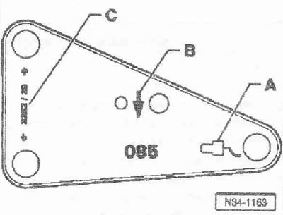
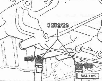
Alignment template -3282/28- parallel to gearbox.
Screw the pin -3282/29- -arrows- into the holes for the bolts securing the bottom bearing of the power unit to the gearbox.
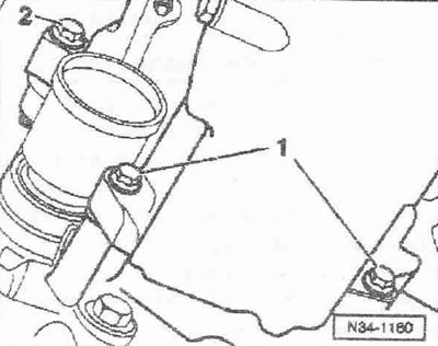
Remove lower bolts -1- and -2- securing engine to gearbox. Press gearbox off dowel sleeves and use spindles to set gearbox holder -3282- to tilt position to left. Carefully lower gearbox with gearbox -VAG 1383 A-. Change the position of the gearbox in the area of the subframe and body on the left by lowering the gearbox mounting with the spindles.
Installation
Instruction. Replace bolts that have been over tightened. Replace self-locking nuts and bolts and seals. rings, seals and seals. cuffs. Secure all hose connections with hose clamps of the correct series. When installing, install all binders in their places.
Tightening torques for gearbox installation
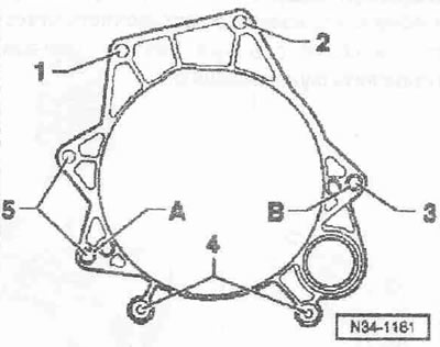
Make sure that bushings -A- and -B- are installed in the cylinder block to align the engine and gearbox; insert bushings if necessary. In the presence of a metal gasket of the engine, take into account the correct fit. Clean input shaft gearing and, if used clutch disc, hub toothing, remove any signs of corrosion and apply a very thin coat of clutch disc gearing grease -G 000 100- to the gearing. Then move the clutch disc in one direction and the other until the hub can easily walk on the shaft. Be sure to remove excess grease.
Carefully raise gearbox using universal tool -3282-. Align the gearbox with the engine and install it.
First screw in and tighten the lower bolts -1- and -2- securing the engine to the gearbox, and then the upper bolts. Install the KP console. Align the power unit with respect to the installation position. To do this, tighten both running screws of the traverse -10.222 A-. Install the gearbox pad. Install the power unit support without tension. Disconnect support bracket -10.222 A- only after tightening all bolts of gearbox bracket to torque. Remove traverse. Install starter. Install reversing light switch -F4-. Vehicles with power steering: install hydraulic lines. Install drive shaft. Install the right drive shaft heat shield. Install pendulum support. Install the front catalytic converter. Install the gear selector.
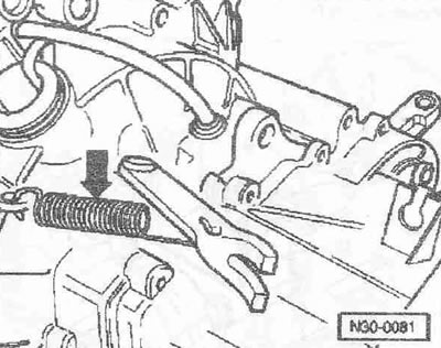
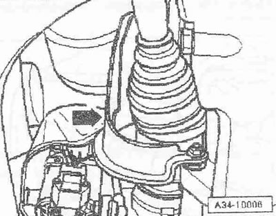
Instruction. On a new gearbox, it is essential to remove the spring -arrow- between the clutch release lever and the gearbox; otherwise the clutch slave cylinder will not function! The spring serves as a transport lock for the clutch release bearing.
Install the clutch slave cylinder bracket. Install the clutch slave cylinder. Check the oil level in the gearbox and add it. Install soundproofing. Install the hydraulic control unit. Pay attention to battery installation work.
Carefully! Risk of damage to control units due to overvoltage. Do not use a charger as a starting aid!
Check the oil level in the reservoir of the clutch drive and the gear shift mechanism; add oil if necessary. Adjust clutch. Carry out the basic setting in the mode "Vehicle self-diagnosis".
Tightening torques
Instruction. The tightening torques are only valid for lightly oiled, oiled, phosphated or burnished nuts and bolts. Additional lubricants such as engine or transmission oil may be used other than graphite-containing lubricants. Do not use degreased parts. Torque tolerance±15%.
| M6 | 9 |
| M7 | 15 |
| M8 | 20 |
| M10 | 40 |
| M12 | 65 |
Heat shield right drive shaft
Tighten bolts for heat shield -arrow- for drive shaft to 23 Nm.
KP console
Tighten bolts -A- of gearbox console -B- to 50 Nm and turn further by 90°.
KP support
Tighten bolts -arrows- for gearbox support to 40 Nm and turn 90°further.
Gearbox to engine
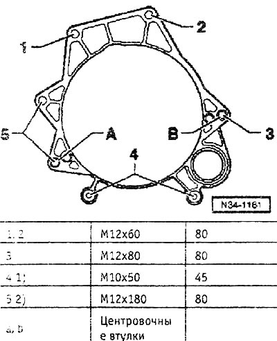
1) Tighten from the engine side.
2) Additionally, mount the starter.
Visitor comments