
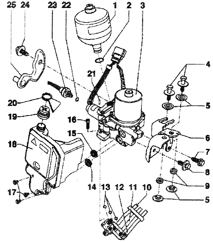
Installation diagram of the hydraulic control unit, receiver:
1. Receiver, 40 Nm
2. O-ring. Replace
3. Hydraulic control unit. Can be checked by measured values and electrical check
4. Combination bolt, 8 Nm
5. Spacer sleeve
6. Hydraulic control unit bracket
7. Bolt, 25 Nm
8. Bolt, 10 Nm
9. Rubber support
10 "12. Pipe" hose line
13. Washers, replace
14/15. O-ring. Replace
16. Bolt, 8 Nm
17. Bolt of the hydraulic control unit feed tank, 5 Nm
18. Feeding tank
19. Cover, 2 Nm
20. Sealing ring. Prevents foreign objects from getting into the ventilation holes of the cover during transportation. After installation, be sure to remove it
21. Bushing
22. Sealing ring. Replace
23. Hydraulic pressure sensor for the "G270" gearbox. Can be checked by measured values and during electrical testing. Remove the wires from the plug connector
24. Bolt, 25 Nm
25. Bracket for mounting the hydraulic control unit on the body