
Table of contents: Removal ↓ Installation ↓
Removal
Caution! Risk of contamination from leaking hydraulic oil. Since the hydraulic pump starts even when the ignition is off, the battery must be disconnected. Risk of damage to electronic components when disconnecting the battery. Carefully monitor the process of removing the battery.
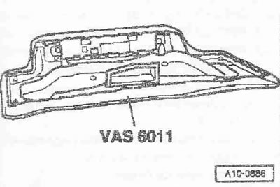
Disconnect the battery ground cable. Wash the outside of the hood and cover it with a protective cover. Unlock the service cover from the inside. Unlock the hood and pull it forward a little. Pull the protective cover "VAS 6011" onto the hood. Do not rest the hood on its edges. Remove the hood and place it on the protective cover "VAS 6011". Loosen the vacuum receiver by approx. 1/2 turn. The hydraulic oil level in the reservoir increases.
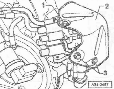
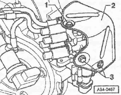
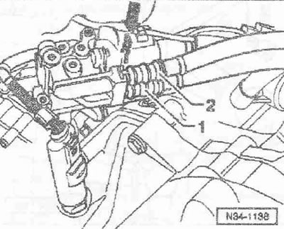
Loosen bolt "1" on top of heat shield "2" of gear shift unit.
Use a screwdriver to remove the clamp of the pipe and hose lines from the gearshift unit. Remove the pipe and hose line "1" and "2" from the gearshift unit. Close the open lines and connections with clean plugs from the plug set for the engine "VAS 6122". Disconnect the plug "3" of the speed sensor "G68".
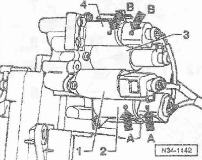
Mark the plug connectors of valves "2" and "4 "with arrows "A, B" for re-installation. Disconnect the plug connectors from the valves "1...4".
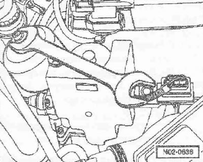
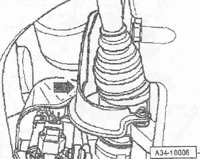
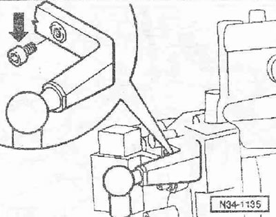
Remove the sound insulation. Unscrew the heat shield "arrow" of the right drive shaft.
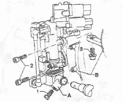
Unscrew bolts "3" and remove heat shield "2" of the gear shift unit.
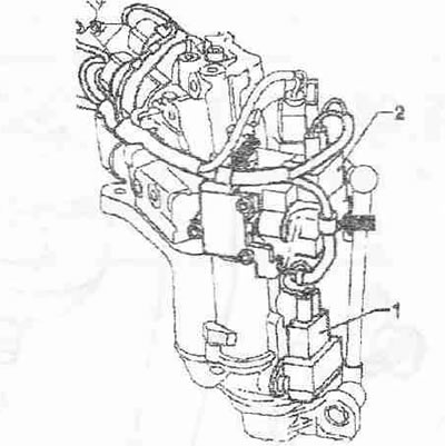
Disconnect the plug connectors "1" and "2" of the gear detection potentiometers "G239 "/" G240". Disconnect the wiring harness from the fasteners on the gearshift unit "arrows" and release the wires.
Loosen bolt "1" and remove gear shift finger "A". Loosen bolts "2" and "3". Remove gear shift unit from gearbox "B" and carefully remove it downwards.
Installation
Installation is in reverse order, taking into account the following: unscrew the transport bolt "arrow".
Clean the threaded hole in the gearshift pin "A" with a tap from the remains of thread varnish. The gearbox must be in neutral. Tighten the gearshift unit bolts. Fasten the wiring harness to the gearshift unit. Connect the plug connectors "1" and "2" of the potentiometers to determine the gear "G239 "/" G240", taking into account the different lengths of the wires. Long wire for potentiometer 1 to determine the gear. "G239". Short wire for potentiometer 2 to determine the gear "G240". Check the wiring and plug connectors according to the wiring diagram. Install noise insulation.
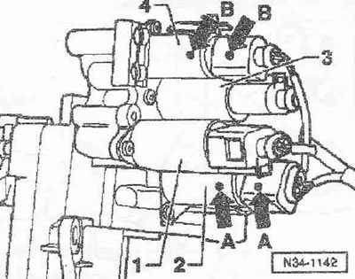
Connect the plug connectors according to the marks marked before removing the "arrows A, B".
- 1. Plug connector for gear selection valve 1 "N₂84"
- 2. Plug connector of the 2nd gear selection valve "N₂85"
- 3. Plug connector for gear selection valve 3 "N₂86"
- 4. Plug connector of the 4th gear selection valve "N₂87"
Check the wiring and plug connectors according to the electrical diagram.
Caution! Damage to the gearshift unit. Ensure that the hose lines are installed in accordance with the color markings. If the hose lines are not installed correctly, the gearshift unit may fail when the ANE is connected.
Connect the plug connector of the speed sensor "G68". Tighten the receiver. Pay attention to the work on installing the battery. Turn on the ignition (the hydraulic fluid level in the expansion tank decreases). Perform a visual inspection of the hydraulic system and ensure that it is tight. Check the oil level in the clutch and gearshift reservoir; add oil if necessary. Adjust the gear shifter.