
Repair Chevrolet Repair Toyota Repair Honda Repair AvtoVAZ Repair Mercedes-Benz Repair BMW Repair Opel
Home  |  Contacts  |  Sitemap  |    
English Русский
Български
Беларускі
Український
Српски
Hrvatski
Română
Polski
Slovenský
Magyar
AudiManual.ru


  • AUDI 80
  • AUDI 100
  • AUDI A3
  • AUDI A4
  • AUDI A6
  • AUDI A8
  • AUDI Q
  • OTHER
  • ARTICLES
Q7 Typ 4L (2005-2015, diesel) Q5 Type 8R (2008-2017)

Fuel Delivery Module and Fuel Level Sensor (Audi Q5-8R)

  • Home
  • Audi Q
  • Q5 Type 8R (2008-2017)
  • Power unit
  • Fuel system (diesel)
  • Fuel Delivery Module and Fuel Level Sensor
            0
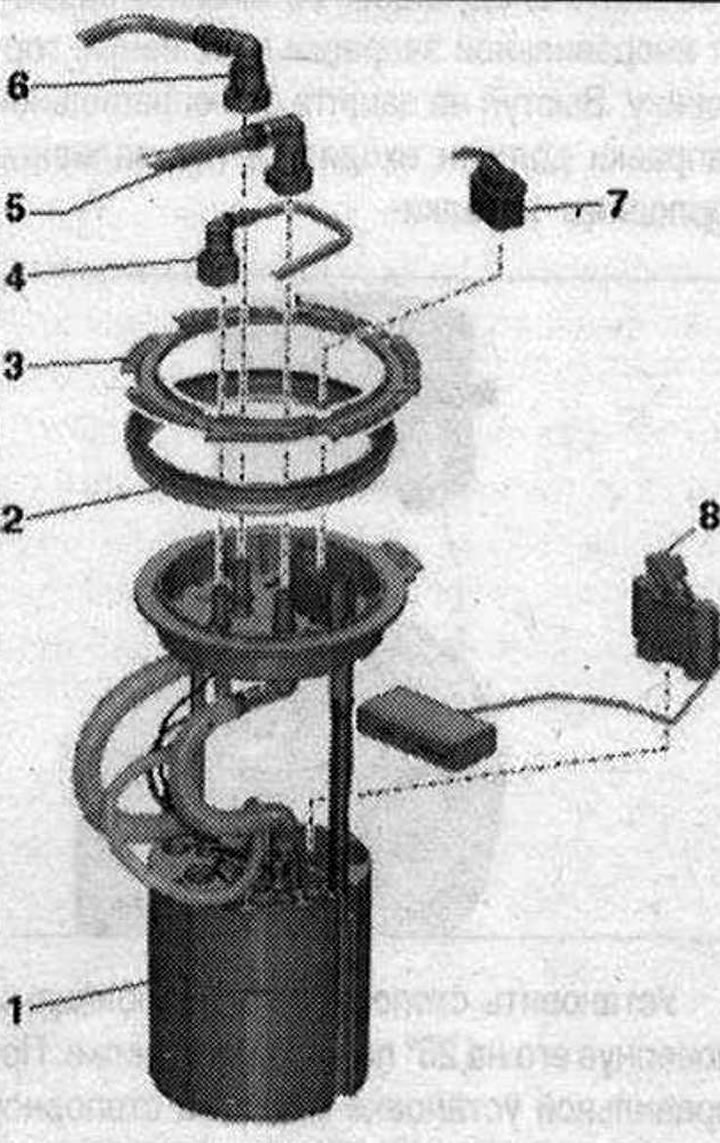
Fuel Delivery Module and Fuel Level Sensor 1. Fuel Delivery Module: Electrical Test of Fuel Booster…

Fuel Delivery Module and Fuel Level Sensor 1. Fuel Delivery Module: Electrical Test of Fuel Booster Pump "G6"; after installation, fill the car with at least 5 liters of fuel; 2. Lip seal: replace; install dry; 3. Locking ring: remove and install using the "T10202" mandrel; tighten to a torque of 110 Nm; 4. Fuel line: to the metering pump on vehicles with independent heating; don't overdo it; to disconnect from the flange, press the fitting lock; clipped to the fuel tank; 5. Fuel supply line: to the regulating valve; don't overdo it; to disconnect from the flange, press the fitting lock; when installing, observe the direction (feed or return), indicated by the arrow on the shut-off flange; clipped to fuel tank; 6. Return fuel line: from the regulating valve; don't overdo it; to disconnect from the flange, press the fitting lock; when installing, observe the direction (feed or return), indicated by the arrow on the shut-off flange; clipped to fuel tank; 7. Electrical plug connection: for fuel pump "G6" and fuel level sensor "G"; 8. Fuel level indicator sensor "G"


Electrical test of fuel booster pump "G6" (in the fuel tank) only vehicles with engine letter: SANA, SANV, CAGA, CAGB, CCWA, CCWB


Use the mounting wedge "3409" "arrow" to pry off the side cover "1" of the front panel on the driver's side and remove it.
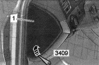


Use the mounting wedge «3409» «arrow» to pry off the side cover «1» of the front panel on the…


Remove fuse 3 on fuse block C "SC3" (ST2 "pos. 2" brown, 3, large fuse on top "arrow"). Connect the remote control device of the VAG 1348 device "V.A.G 1348/3A" with adapter cable -VAG 1348/3 "2" to the right terminal of the fuse base "SC3". Route the remote control switch forward into the engine compartment.
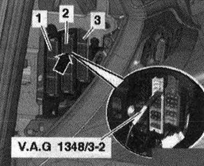
Remove fuse 3 on fuse block C «SC3» (ST2 «pos. 2» brown, 3, large fuse on top «arrow»). Connect the…


Unlock and remove cover "2" by pressing the place marked with "arrow A". Unlock the lock "arrow B" and open cover "1".
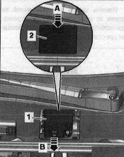
Unlock and remove cover «2» by pressing the place marked with «arrow A». Unlock the lock «arrow B»…


Connect the clamp terminal to the terminal of the external starter current source "U6" "pos. 1" in the terminal block for terminal 30 "TV22" in the water drainage box. Do not take "pos. 2" into account.
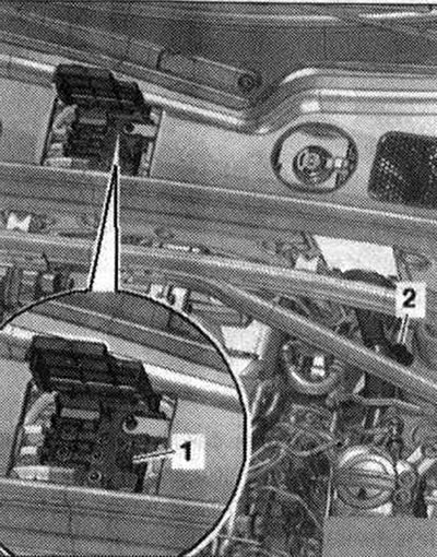


Connect the clamp terminal to the terminal of the external starter current source «U6» «pos. 1» in…


Press the remote control switch. You should be able to hear the pump running. The fuel pump runs very quietly. Avoid any extraneous noise during the test.

If the pump operation is not audible: Remove 1/3 of the rear seat on the right. Unscrew the bolts "arrows" and remove the cover "1" of the shut-off flange. Disconnect the plug "1" from the flange.
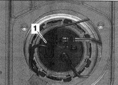
If the pump operation is not audible: Remove 1/3 of the rear seat on the right. Unscrew the bolts…


To do this, move the stopper "1" in the upward direction "arrow A" and press the release button inward "arrow B".
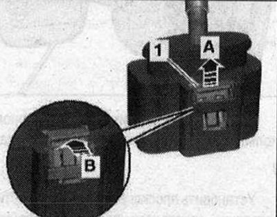
To do this, move the stopper «1» in the upward direction «arrow A» and press the release button…


Connect a multimeter to measure the voltage between pins "1" and "5" of the plug connector. Press the remote control switch.
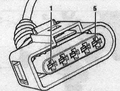


Connect a multimeter to measure the voltage between pins «1» and «5» of the plug connector. Press…


Set value: approximate battery voltage. If the set value is not reached: repair the wire break according to the wiring diagram. If the set value is reached, although the sound of the operating pump is not heard: remove the fuel supply unit. Check the correct connection and patency of the electrical wires between the flange and the fuel pump. If no damage to the wires is found, replace the fuel supply module. Install the fuel supply module.
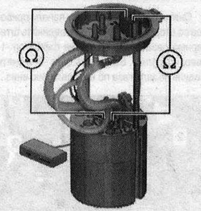
Set value: approximate battery voltage. If the set value is not reached: repair the wire break…
The article was checked by auto expert Timur Bazhenov
This article is available at russian, bulgarian, belarusian, ukrainian, serbian, croatian, romanian, polish, slovak, hungarian

Share information:
Previous articles
Audi Q Q5 Type 8R: Fuel system (diesel)
Next articles

Disable protection against incorrect filling
Fuel filler flap
Removal the fuel tank with attachments
Fuel tank with attachments
Removal the fuel supply unit
Checking the fuel level sensor «G»
Removal the fuel level sensor «G»
Fuel filter and additional fuel pump «V393»


Similar articles on other Audi car models:
Fuel level sensor — removal and installation Audi 80 B3 (1986-1991, petrol)
Fuel level sensor — removal and installation Audi 100 C3 (1982-1990, diesel)
Removal and installation the fuel pump / fuel level sensor Audi A3 Type 8L (1996-2003)
Removal and installation a fuel pump with a fuel level sensor Audi A4 B6 (2000-2006)
Fuel pump/fuel level sensor Audi A6 C5 (1997-2004)
Fuel pump / fuel level sensor Audi A8 D2 (1994-2002)
Fuel pumping unit and fuel level indicator sensor Audi A2 (1999-2005)
Link to this page in different formats


Visitor comments

No comments yet


How much will 46 + 19 =


Q7 4L(2005-2015, diesel) 
  • General information
  • Operating instructions
  • Maintenance
  • Power unit
  • Diesels 3.0 l (BUG, BUN, CAS)
  • Diesels 3.0 l (CATA, CCMA)
  • Diesels 3.0 l (CJGA/CJGC)
  • Diesels 4.2 l (BTR, CCFA/CCFC)
  • Cooling system
  • Fuel and exhaust system
  • Engine management system
  • Starting and charging
  • Transmission
  • Automatic gearbox
  • Drive shafts
  • Chassis
  • Brake system
  • Front suspension
  • Rear suspension
  • Steering system
  • Body
  • Air conditioner
  • Exterior
  • Interior
  • Electrical equipment
  • Equipment and devices
  • Electrical circuits
 
Q5 8R(2008-2017) 
  • General information
  • User manual
  • Power unit
  • Petrol engine 2.0 l
  • Petrol engine 3.2 l
  • Fuel system (petrol)
  • Diesel 2.0 liter (CA)
  • Diesel 2.0 liter (CG/CJ/CM)
  • Diesel engine 3.0 l
  • Fuel system (diesel)
  • Transmission
  • Manual gearbox 0B1
  • Manual gearbox 0B2
  • Automatic gearbox 0B5
  • Automatic gearbox 0B6
  • Chassis
  • Front suspension
  • Rear suspension
  • Brake system
  • Steering
  • Body
  • Exterior
  • Interior
  • Doors, locks and windows
  • Safety system
  • Ventilation and heating
  • Electrical equipment
  • Power devices
  • Equipment and devices
  • Lighting and alarm
  • Audio system
  • Electrical circuits
 
AudiManual.ru © 2017-2026 · Mobile version · Feedback · Sitemap: EN BG BY UA RS HR RO PL SK HU · Site search · News and articles
80 B2 · 80 B3 petrol · 80 B3 · 80 B4 · 100 C3 diesel · 100 C3 petrol · 100 C3 · 100 C4 petrol · 100 C4 · A3 Type 8L · A4 B5 petrol · A4 B5 · A4 B6 petrol · A4 B6 · A4 B7 · A4 B8 · A6 C4 · A6 C5 · A6 C5 Allroad · A8 D2 · Q5 Type 8R · Q7 Typ 4L · Audi A2 ·
This site uses cookies 🍪. Click the button to accept this fact.