Repair Chevrolet Repair Toyota Repair Honda Repair AvtoVAZ Repair Mercedes-Benz Repair BMW Repair Opel
Home  |  Contacts  |  Sitemap  |    
English Русский
Български
Беларускі
Український
Српски
Hrvatski
Română
Polski
Slovenský
Magyar
AudiManual.ru


  • AUDI 80
  • AUDI 100
  • AUDI A3
  • AUDI A4
  • AUDI A6
  • AUDI A8
  • AUDI Q
  • OTHER
  • ARTICLES
Q7 Typ 4L (2005-2015, diesel) Q5 Type 8R (2008-2017)

Removal the support bracket. Cars with manual transmission (Audi Q5-8R)

  • Home
  • Audi Q
  • Q5 Type 8R (2008-2017)
  • Chassis
  • Brake system
  • Removal the support bracket. Cars with manual transmission
            0
Removal the support bracket. Cars with manual transmission


Removing the instrument panel cover on the driver's side "1...3"

Removing the instrument panel cover on the driver's side «1...3»


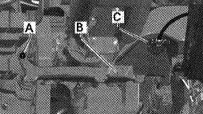
Disconnect the electrical connection of the air duct for the footrest "C". Remove the air duct for the footrest "A-B".

Disconnect the electrical connection of the air duct for the footrest «C». Remove the air duct for…


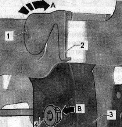
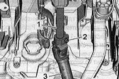
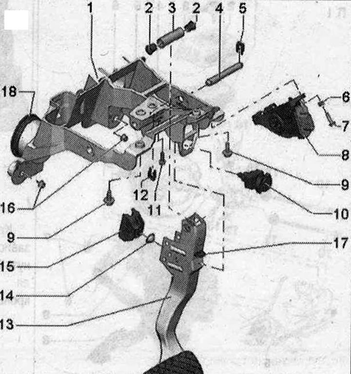
Remove the brake light sensor. Disconnect the plug connector from the gas pedal module. Disconnect the brake pedal from the brake booster. If possible, leave the brake pedal stop in place; abrupt release of the brake pedal may cause breakage of the brake light sensor bracket. Remove servo spring "2" from clutch pedal "1"


Remove the brake light sensor. Disconnect the plug connector from the gas pedal module. Disconnect…


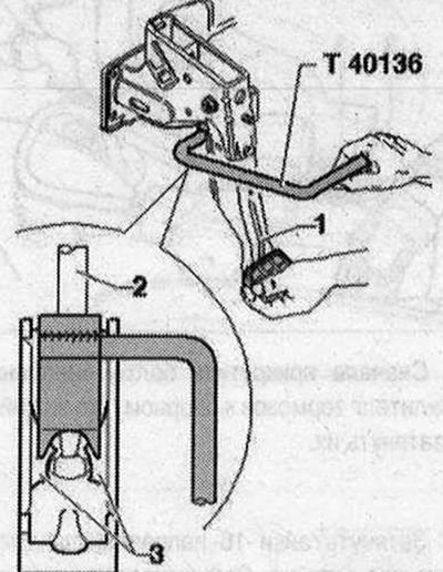
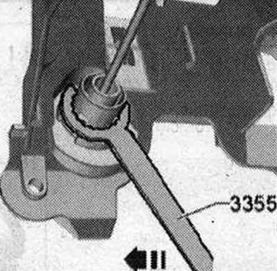
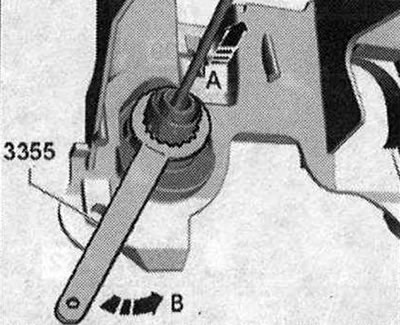
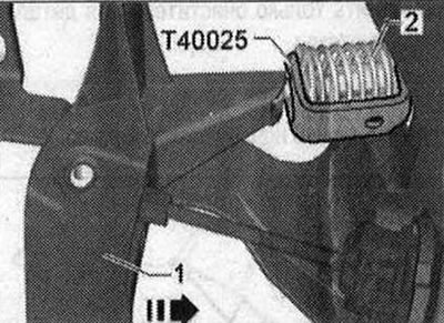
During subsequent installation, take into account the correct mounting position of the servo spring. Remove the bolt securing the clutch pedal to the clutch master cylinder "4" from the pedal bracket. Unlocking the locks "1 and 2" occurs only when removed. Unlock the master cylinder with the puller "3355". Turn the tool clockwise "arrow".

During subsequent installation, take into account the correct mounting position of the servo…


Remove the stretcher. Remove the wall of the water-diverting box. Remove the cover "2" above the coolant expansion tank.

Remove the stretcher. Remove the wall of the water-diverting box. Remove the cover «2» above the…


Removal the support bracket. Cars with manual transmission

I


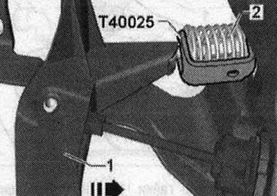
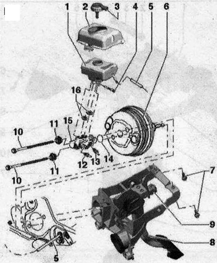
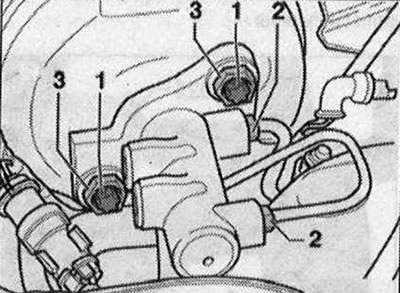
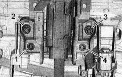
The cover is installed depending on the model. Unscrew the bolts "1" securing the brake booster to the support bracket.

The cover is installed depending on the model. Unscrew the bolts «1» securing the brake booster to…


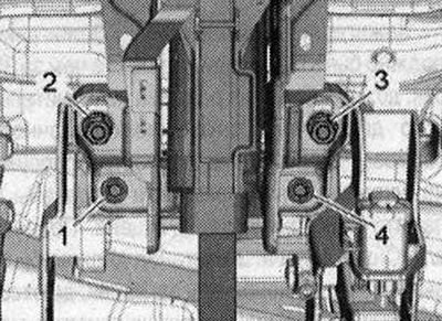
Unscrew the nuts "16" of the support bracket guides.

Unscrew the nuts «16» of the support bracket guides.


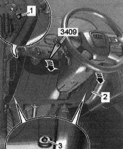
Set the steering wheel with the steering column adjuster as far back as possible, in the direction of the driver's seat. Set the steering wheel to the straight-ahead position. The wheels are straight. To remove the steering column, do not remove the instrument cluster and steering wheel. Unscrew bolt "2" from the bottom of the steering column.

Set the steering wheel with the steering column adjuster as far back as possible, in the direction…


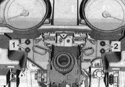
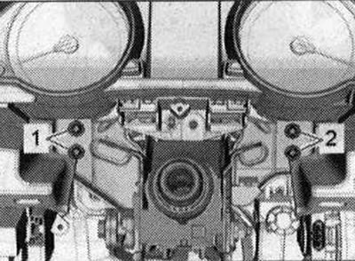
Remove the lower bolts "2...4" of the steering column and support bracket.


Remove the lower bolts «2...4» of the steering column and support bracket.


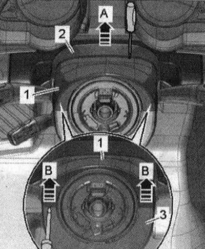
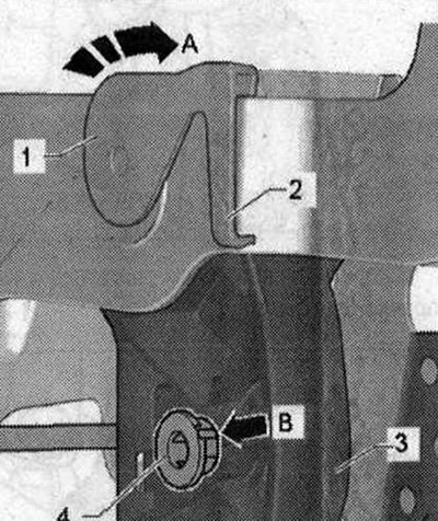
Remove the joint cover "2" from the upper trim "1" of the steering column switch module (SMLS) "arrow A". Remove the cable guides from the steering column.

The steering wheel is not shown in the picture. Do not remove the steering wheel and instrument cluster. Remove the bolts "1 and 2" of the steering column from the central tube, supporting the column with your hand from below.

The steering wheel is not shown in the picture. Do not remove the steering wheel and instrument…


Loosen and loosen bolts "1 and 2" with a standard 3/8-inch square ratchet and a toothed extension attachment. Remove the steering column from the steering shaft. Carefully remove the steering column from the steering wheel. Remove the support bracket from the vehicle. When removing the support bracket, note that the clutch master cylinder must not be removed from the hydraulic line. The main working cylinder of the clutch remains in the vehicle.


Installation


If possible, leave the brake pedal stop in place; abrupt release of the brake pedal may cause breakage of the brake light sensor bracket. Before installing the support bracket, make sure that the clutch master cylinder gasket is correctly positioned. Insert the support bracket into the guides in the car. Guide the clutch master cylinder through the hole in the support bracket so that the cylinder mounts are installed in the support bracket. Install the nuts on the support bracket guides and tighten them on the support bracket. Screw in and tighten the bolts "1" securing the brake booster to the support bracket.

If possible, leave the brake pedal stop in place; abrupt release of the brake pedal may cause…


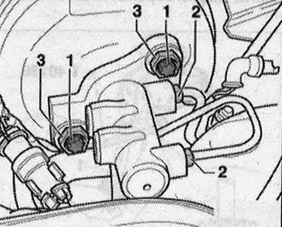
First, screw the brake booster mounting bolts to the support bracket and tighten them.

Removal the support bracket. Cars with manual transmission

I


Tighten nuts "16" of the support bracket guides. Fix the master cylinder with puller "3355". Turn the tool counterclockwise "arrow B", while pulling the master cylinder forward "arrow".

Tighten nuts «16» of the support bracket guides. Fix the master cylinder with puller «3355». Turn…


Insert bolt "4" securing the clutch pedal to the clutch master cylinder and press the bolt flush. Observe the mounting position of the bolt. The groove on bolt "B" must match the groove on the pedal bracket.

Insert bolt «4» securing the clutch pedal to the clutch master cylinder and press the bolt flush.…


Insert servo spring "2" into the clutch pedal. Connect the plug connector of the gas pedal module.

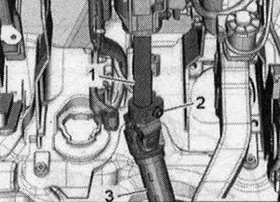
Connecting the brake pedal to the brake booster: Hold the ball head of the push rod in front of the fastener and press the brake pedal towards the brake booster until the ball head clicks into place with an audible click. Install the brake light sensor. Insert the steering column "1" into the steering shaft "3". Install the steering column on the central tube and insert the bolts.


Connecting the brake pedal to the brake booster: Hold the ball head of the push rod in front of the…


Take into account the different lengths of the bolts. Tighten bolts "1 and 2" crosswise to a torque of 20 Nm.

Take into account the different lengths of the bolts. Tighten bolts «1 and 2» crosswise to a torque…


Tighten bolts "1 and 2" with a standard 3/8-inch square ratchet and a toothed extension attachment. Tighten the bolts with a torque wrench and ratchet "V.A.S 5122" with extension, tightening torque 20 Nm. Install the slotted cover of the upper trim of the steering column switch unit (steering column switch module). Install the cable guides from the steering column. Tighten the steering shaft bolt "2" to 20 Nm.

Insert the lower bolts "1 to 4" of the steering column and support bracket and tighten to 20 Nm.

Insert the lower bolts «1 to 4» of the steering column and support bracket and tighten to 20 Nm.


Install the footwell air duct "A-B". Tighten the footwell air duct bolt "A". Connect the footwell air duct electrical connection "C".


Install the footwell air duct «A-B». Tighten the footwell air duct bolt «A». Connect the footwell…


Install the instrument panel cover on the driver's side "1...3". Install the cover "2" over the coolant expansion tank. The cover "2" is installed depending on the model. Install the water drain box wall. Install the brace.

(The original source of the article can be found on the website: AUDIMANUAL.ru)
The article was checked by auto expert Timur Bazhenov
This article is available at russian, bulgarian, belarusian, ukrainian, serbian, croatian, romanian, polish, slovak, hungarian

Share information:
Previous articles
Audi Q Q5 Type 8R: Brake system
Next articles

Installing the brake pedal with the support bracket removed
Removal the brake pedal. Cars with manual transmission
Connecting the brake pedal to the brake booster
Disconnecting and connecting the brake pedal and brake booster
Electronic Parking Brake (EPB)
Removal the electronic parking and handbrake control unit J540
Removal the actuator motor of the electronic parking and hand…
Checking for leaks by pressing the brake pedal


Similar articles on other Audi car models:
Maintenance of manual transmission Audi 80 B3 (1986-1991, petrol)
Manual Transmission Specifications Audi 100 C3 (1982-1990, diesel)
Removal and installation of engine / manual transmission Audi A3 Type 8L (1996-2003)
Removal and installation of manual transmission Audi A4 B6 (2000-2006)
Removal and installation of manual transmission Audi A6 C4 (1994-1997)
Removal and installation of a manual transmission Audi A8 D2 (1994-2002)
Removal and installation the additional units bracket Audi A2 (1999-2005)
Link to this page in different formats


Visitor comments

No comments yet


How much will 30 + 45 =


Q7 4L(2005-2015, diesel) 
  • General information
  • Operating instructions
  • Maintenance
  • Power unit
  • Diesels 3.0 l (BUG, BUN, CAS)
  • Diesels 3.0 l (CATA, CCMA)
  • Diesels 3.0 l (CJGA/CJGC)
  • Diesels 4.2 l (BTR, CCFA/CCFC)
  • Cooling system
  • Fuel and exhaust system
  • Engine management system
  • Starting and charging
  • Transmission
  • Automatic gearbox
  • Drive shafts
  • Chassis
  • Brake system
  • Front suspension
  • Rear suspension
  • Steering system
  • Body
  • Air conditioner
  • Exterior
  • Interior
  • Electrical equipment
  • Equipment and devices
  • Electrical circuits
 
Q5 8R(2008-2017) 
  • General information
  • User manual
  • Power unit
  • Petrol engine 2.0 l
  • Petrol engine 3.2 l
  • Fuel system (petrol)
  • Diesel 2.0 liter (CA)
  • Diesel 2.0 liter (CG/CJ/CM)
  • Diesel engine 3.0 l
  • Fuel system (diesel)
  • Transmission
  • Manual gearbox 0B1
  • Manual gearbox 0B2
  • Automatic gearbox 0B5
  • Automatic gearbox 0B6
  • Chassis
  • Front suspension
  • Rear suspension
  • Brake system
  • Steering
  • Body
  • Exterior
  • Interior
  • Doors, locks and windows
  • Safety system
  • Ventilation and heating
  • Electrical equipment
  • Power devices
  • Equipment and devices
  • Lighting and alarm
  • Audio system
  • Electrical circuits
 
AudiManual.ru © 2017-2026 · Mobile version · Feedback · Sitemap: EN BG BY UA RS HR RO PL SK HU · Site search · News and articles
80 B2 · 80 B3 petrol · 80 B3 · 80 B4 · 100 C3 diesel · 100 C3 petrol · 100 C3 · 100 C4 petrol · 100 C4 · A3 Type 8L · A4 B5 petrol · A4 B5 · A4 B6 petrol · A4 B6 · A4 B7 · A4 B8 · A6 C4 · A6 C5 · A6 C5 Allroad · A8 D2 · Q5 Type 8R · Q7 Typ 4L · Audi A2 ·
This site uses cookies 🍪. Click the button to accept this fact.