
Table of contents: Parts and units ABS/ESP Bosch 8.1 ↓ Audi Start Assist ↓
The anti-lock braking system does not require maintenance in principle. Inspection, installation and repair work may only be performed by trained specialists. Ignoring the points specified in the repair manual may damage the system and reduce safety when driving the vehicle. Before carrying out repair work on the anti-lock braking system, it is necessary to establish the cause of its damage using the self-diagnosis function. When installing a new hydraulic control unit, it is necessary to check its coding. Tester "VAS 5051 B" or use "VAS 5052". Before installation work, turn on the ignition. For vehicles with a coded radio, request the security code and disconnect the flat ground wire from the battery. When handling brake fluid, observe the current regulations and safety instructions. For any work requiring opening the hydraulic system, it is necessary to bleed the brake system using the device for filling and bleeding the brake system "VAS 5234". In addition, the brake The system should be tested at high and low pressure. During the final test drive, perform at least one braking application with the anti-lock system engaged (there should be a noticeable pulsation in the brake pedal), see tester "VAS 5051 B" or "VAS 5052". When repairing the anti-lock braking system, pay particular attention to the requirements for maintaining cleanliness; under no circumstances may petroleum products such as plastic oils, greases, etc. be used. The connection points and the area around them must be thoroughly cleaned before disconnecting; do not use aggressive cleaning agents such as brake cleaner, gasoline, thinners, or similar agents. Place the removed parts on a clean surface and cover them. If repairs are postponed, cover and protect the removed parts. (Use plugs from repair kit 1 NO 698 311 A). Do not use rags that leave fibres! Remove spare parts from packaging only immediately before installation. Use original parts only in original packaging. If the system is open, do not work with compressed air or move the car. Do not allow brake fluid to enter electrical connectors.
Parts and units ABS/ESP Bosch 8.1
The Bosch ESP 8.1 system features the following functions: ABS - anti-lock braking system, ASR - anti-slip system, EBV - electronic brake force distribution system, EDS - electronic differential lock, ESP - electronic stability control system, FBS - brake overheating protection system (fading brake support), HBA - hydraulic brake booster, MSR - engine braking regulator, emergency brake system signal, brake disc cleaner, trailer stabilization system.
The brake system has a diagonal division. The brake system is amplified by a vacuum booster. ABS malfunctions do not affect the brake system and its amplification. The brake system performs its functions even if the ABS fails. However, if the ABS fails, you should take into account the change in the ratio of braking forces on the axles. After the ABS warning lamp lights up, the rear wheels may lock prematurely when braking. Due to the direct connection of these components, the number of error sources is reduced. The components cannot be repaired; they can only be replaced.
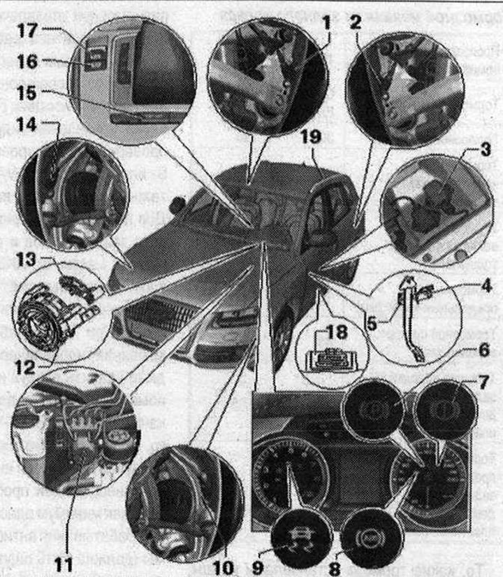
Parts and units ABS/ESP Bosch 8.1 1. Rear right wheel speed sensor G44. Can be checked in the "Guided Fault Finding" mode using the "VAS 5051 B" or "VAS 5052" diagnostic complex; 2. Rear left wheel speed sensor G46; 3. ESP sensor "G419". Installation location: under the left front seat. 9 Nm. Combined lateral acceleration sensor "G200", yaw rate sensor "G202" and longitudinal acceleration sensor "G251". Can be checked in "Guided Fault Finding" mode using the "VAS 5051 B" or "VAS 5052" diagnostic system. Observe installation instructions. When installing, ensure that the arrow points in the direction of travel; 4. Brake light sensor. Installation location: on the brake pedal. Can be checked in the "Guided Fault Finding" mode using the "VAS 5051 B" or "VAS 5052" diagnostic complex. Can be reused after removal; 5. Brake pedal with brake light sensor mount; 6. Electromechanical parking brake indicator lamp. Installation location: in the speedometer, lights up when the parking brake and ignition are on, lights up for 30 seconds when the parking brake is on and the ignition is off, flashes after the parking brake is applied if the braking force is insufficient to prevent the car from rolling back. The indicator lamp goes out when the parking brake is off; 7. Brake system indicator lamp. Installation location: in the speedometer, lights up together with the ABS indicator lamp when the ABS system fails. Flashes when the brake fluid level is low. Flashes when the brake system is faulty. When the "SET button" is pressed, a detailed description of the malfunction is displayed on the instrument cluster; 8. Anti-lock braking system (ABS) indicator lamp. The indicator lamp covers the ABS system and the electronic differential lock (EDS). Installation location - in the speedometer. Lights up for a few seconds when the ignition is turned on and goes out after the automatic, self-diagnosis of the ABS system, if no faults are detected. A fault is detected in the ABS system if the indicator lamp: does not light up when the ignition is turned on, does not go out after a few seconds, lights up during the trip. The car can be stopped using the service brake system. It is necessary to take into account the change in the nature of braking. The electronic differential lock (EDS) and the ABS system work together. If the EDS fails, the ABS indicator lamp lights up; 9. Electronic Stability Program (ESP/ASR) indicator light. Installation location: in the tachometer. Flashes while driving if the ESP/ASR system is activated. Lights up when the ignition is switched on and goes out after a short self-diagnosis. Lights up when a fault occurs in the ESP system. Lights up when a fault occurs in the ABS system, since ESP and ABS work together. Lights up when ESP/ASP is switched off. Lights up during the adaptation process of the sensor technology in cases where the following occurs: the battery was disconnected and reconnected, the engine was started from an external source of starter current, the battery charge is too low. At the end of the adaptation process of the sensor technology after a short distance, the ESP indicator light goes out; 10. Front left wheel speed sensor G47. Can be checked in the "Guided Fault Finding" mode using the "VAS 5051 B" or "VAS 5052" diagnostic complex; 11. Hydraulic block N55 with used L 04; 12. Return ring. Installation location: on the steering column together with the contact ring; 13. Steering wheel angle sensor "G85". Location: the sensor is installed on the steering column contact ring. Perform zero correction using the "VAS 5051B" or "VAS 5052" tester; 14. Front right wheel speed sensor G45; 15. ASR/ESP button "E256". The installation location depends on the model. Switching the ESP/ASR system on and off; 16. Hill Start Assist Pressure Sensor (Audi Hold Assist). Installation location: in the center console; 17. Electromechanical parking brake switch "F234". Installation location: in the center console; 18. Diagnostic connector. Installation location: trim in the driver's footwell area; 19. Roof rack recognition sensor "G625"
Note. The roof rack recognition sensor "G625" for right and left-hand drive vehicles is installed only in the left roof rail. The sensor cannot be replaced as a separate component and is integrated into the left roof rail.
Audi Start Assist
Function: The assistant helps the driver in cases where it is necessary to frequently or for a long time hold the car with the engine running in place. When the function is activated, the stopped car is held by the start assist. The driver can take his foot off the brake pedal. At first, the car is held in place by maintaining the brake pressure in the ESP system on all 4 wheels. In order to avoid overheating of the ESP electromagnetic valves during long-term parking, starting from a temperature of the electromagnetic valves of 200°C, the braking force is automatically transferred to the rear electromechanical parking brake. Automatic determination of the moment of brake release is carried out on the basis of the following parameters: engine torque; slope angle; gear engaged; on cars with manual transmission - clutch pedal travel (registered by the clutch sensor); on cars with automatic transmission - the beginning of the torque converter closing. In order to prevent the car from rolling, the brake is released only when sufficient engine torque is reached.
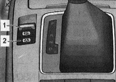
Activation: To activate the "stand by" function, the following conditions must be met: the driver is wearing a seat belt; the engine is running; the driver's door is closed; there are no faults in the ESP system and the electronic parking brake. Activation is carried out by pressing the switch "2" on the central console. The switch displays the following modes: deactivated, the switch LED is off; "stand by", the switch LED is on; active, the switch LED lights up and the instrument cluster displays "P" in green. The transfer of braking force from the ESP to the electronic parking brake occurs only when the instrument cluster displays "green P" and when: the temperature of the ESP electromagnetic valves is at least 200°C; opening the driver's door; unfastening the driver's seat belt; engine stop; turning off the ignition; pressing the switch; pressing the accelerator or brake pedal. When pressing the hill start assist (ANA) switch, do not press the foot brake pedal. When the braking force is transferred from the ESP system to the electronic parking brake, the "green P" indicator on the instrument cluster changes to "red P".
(Information obtained from this resource: Audimanual.ru)