
Table of contents: Removal ↓ Installation ↓
Removal
Cars with 2.7L engine
1. Unscrew the bolts (see arrows in the illustration) and remove the engine protective covers A-C.
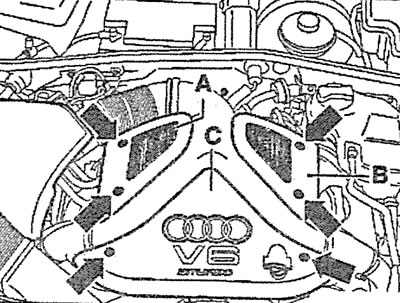
2.1. Unscrew the bolts (see arrows) and remove the engine protective covers A-C
2. Unscrew the holder bolts, loosen the fastening clamps (see arrows in the illustration) and disconnect the air ducts.
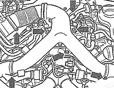
2.2. Unscrew the holder bolts, loosen the fastening clamps (see arrows) and disconnect the air ducts
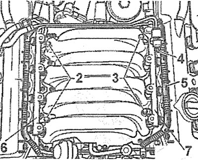
3. Press the clamps and remove the boost air pressure reducing valve 1 (see illustration 2.0).
4. Disconnect the plug of the solenoid valve 2 for purging the adsorber (see illustration 2.0).
5. Remove both exhaust gas temperature sensors 3 without disconnecting the plugs from them (see illustration 2.0), and also remove the afterburning system pump from the intake manifold.
6. Disconnect the low pressure hose 4 of the brake booster (see illustration 2.0).
7. Disconnect the plug of the turbocharger bypass valve 5 (see illustration 2.0).
8. Remove the low pressure hose 6 of the vacuum receiver (see illustration 2.0).
9. Disconnect the 7 fuel injector power supply connectors on both cylinder heads (see illustration 2.0).
10. Disconnect the air intake hose 8 (see illustration 2.0).
11. Disconnect the throttle valve plug 9 (see illustration 2.0).
12. Disconnect plug 10 of the boost pressure sensor (see illustration 2.0).
13. Disconnect the supply air ducts 11 (see illustration 2.0).
14. Disconnect the air hose 12 (see illustration 2.0).
15. Disconnect plug 13 of the intake air temperature sensor (see illustration 2.0).
16. Remove the crankcase ventilation hose 14 (see illustration 2.0).
17. Disconnect the air intake hose 15 (see illustration 2.0).
18. Disconnect the return fuel line 16 from the fuel rail (see illustration 2.0). Collect any leaking fuel with a clean cloth.
19. Disconnect the fuel supply line 17 from the fuel rail (see illustration 2.0).
20. Unscrew the bolts securing the intake manifold to the cylinder heads and carefully remove the manifold. The tightening torque of the bolts is 10 Nm.
Cars with 4.2L engine
21. Install the upper front cross member in the service position (see paragraphs 5.1-5.15 of the chapter "Alternator drive V-belt - removal and installation" in Section 2B).
22. Remove the upper engine protective covers (see arrows in the illustration).
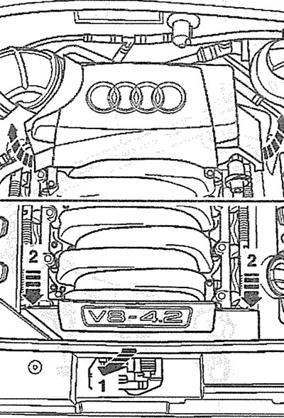
2.22. Remove the upper engine protective covers (see arrows)
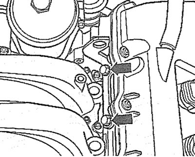
23. Disconnect the low pressure hoses by removing the fastening clamps (see arrows in the illustration).
2.23. Disconnect the low pressure hoses by removing the fastening clamps (see arrows)
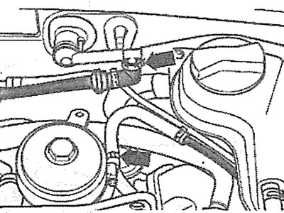
24. Disconnect the low pressure hose from the intake manifold (see arrow in illustration).
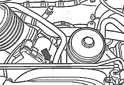
2.24. Disconnect the low pressure hose from the intake manifold (see arrow)
25. Disconnect plug 1 from the throttle valve (see illustration).
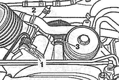
2.25. Disconnect plug 1 from the throttle valve
26. Disconnect the air duct by removing clamp 2 (see illustration 2.25).
27. Disconnect the crankcase ventilation hose from the intake manifold by removing clamp 3 (see illustration 2.25).
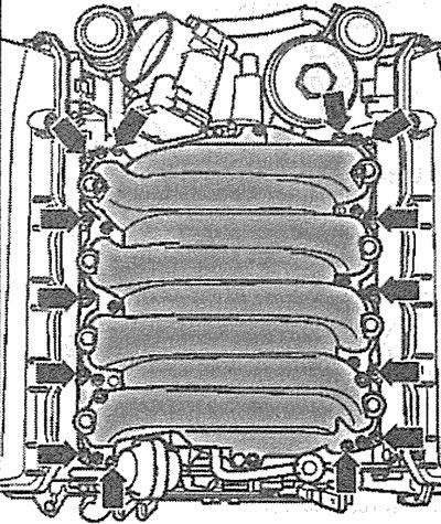
28. Disconnect plugs 1-6 on the intake manifold (see illustration).
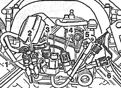
2.28. Disconnect plugs 1-6 on the intake manifold
29. Disconnect the low pressure hose (see arrow in illustration).
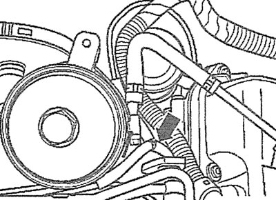
2.29. Disconnect the low pressure hose (see arrow)
30. Disconnect the fuel injector plugs on rails 6 and 7, the wires of which are combined into harnesses 1 and 5 (see illustration).
2.30. Disconnect the fuel injector plugs on rails 6 and 7, the wires of which are combined into harnesses 1 and 5
31. Disconnect low pressure hose 4 from the fuel pressure regulator (see illustration 2.30).
32. Unscrew bolts 2 and 3 and remove rails 6 and 7 together with fuel injectors (see illustration 2.30).
33. Unscrew the mounting bolts (see arrows in the illustration) and remove the rear left engine lifting eye.
2.33. Unscrew the mounting bolts (see arrows) and remove the rear left engine lifting eye
34. Unscrew the mounting bolts (see arrows in the illustration) and remove the intake manifold.
2.34. Unscrew the mounting bolts (see arrows) and remove the intake manifold
Installation
The intake manifold is installed in the reverse order of removal.
35. Cars with 4.2L engine. Replace the intake manifold seals by unscrewing bolts 1 and 2 (see illustration).
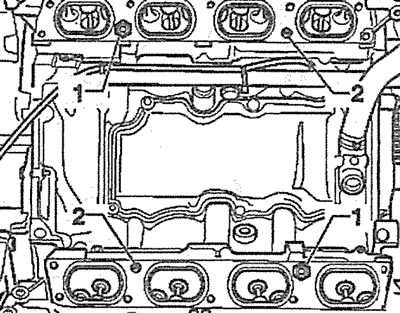
2.35. Replace the intake manifold seals by unscrewing bolts 1 and 2. Cars with a 4.2 L engine