
Table of contents: Removal ↓ Installation ↓
Attention! The procedure is given using the example of cars with a 2.7 liter engine.
Attention! The fuel rail, consisting of two parts, functions as a single unit due to the presence of connecting fuel lines (see illustration 3.0).
Removal
1. Unscrew the bolts (see arrows in the illustration) and remove the engine protective covers A-C.
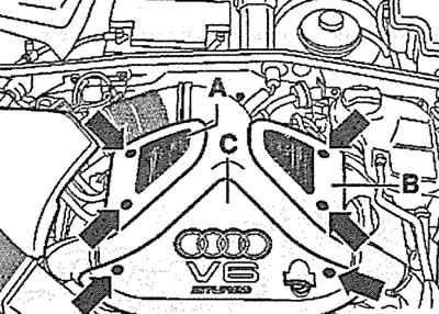
3.1. Unscrew the bolts (see arrows) and remove the engine protective covers A-C
2. Unscrew the holder bolts, loosen the fastening clamps (see arrows in the illustration) and disconnect the air ducts.
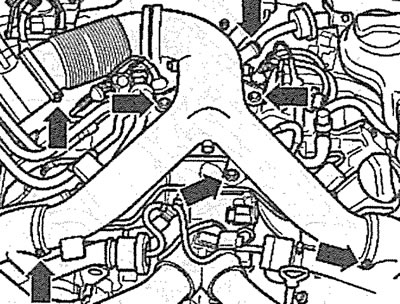
3.2. Unscrew the holder bolts, loosen the fastening clamps (see arrows) and disconnect the air ducts
3. Remove the fuel pressure reducing valve 1 (see illustration 3.0a).
4. Disconnect the plug of the solenoid valve 2 for purging the adsorber (see illustration 3.0a).
5. Disconnect the plug of the turbocharger bypass valve 3 (see illustration 3.0).
6. Remove clamps 4 (see illustration 3.0a) and disconnect the hoses from the turbocharger bypass valve.
7. Remove the clamps of the fuel pressure regulator 6 and disconnect the hose (see illustration 3.0).
8. Disconnect the fuel injector power supply connectors 6 (see illustration 3.0).
9. Remove the fastening clamps and disconnect the low pressure hose 7.
10. Remove the clamps and disconnect the air intake hoses 8 (see illustration 3.0).
11. Remove the fastening clamps and disconnect the low pressure hose 9 (see illustration 3.0).
Caution! The fuel system is under pressure. Before disconnecting fuel hoses or fuel lines, cover the joint with a rag.
12. Loosen the union nut securing the fuel supply line and release the pressure in the system.
13. Unscrew the bolts (see arrows in illustration 3.0) fastenings of the fuel rail and remove the rail together with the injectors. The tightening torque of the bolts fastening the fuel rail to the intake manifold is 10 Nm.
Installation
The fuel rail is installed in the reverse order of removal.
(The original article is posted on the resource: AUDImanual)