
Table of contents: Removal ↓ Installation ↓
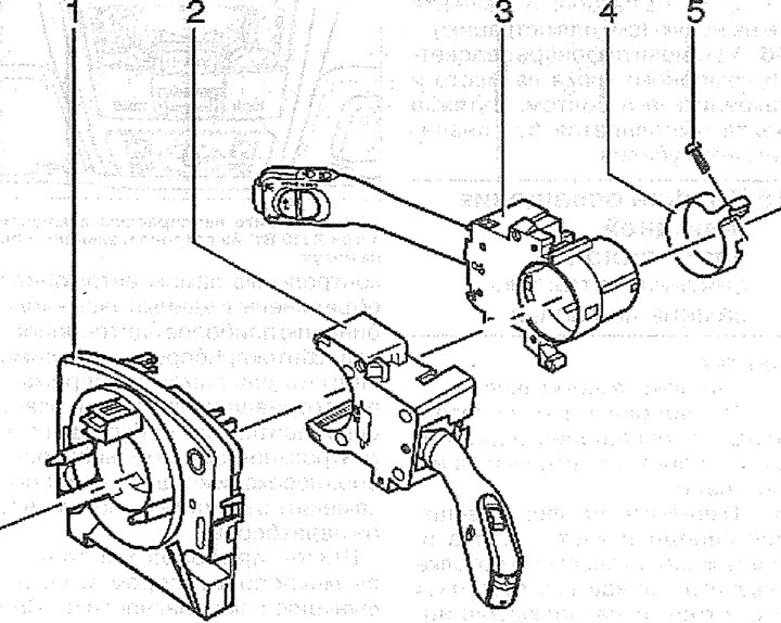
17.0. Steering column switch block:
1 - contact ring and steering wheel angle sensor
2 - windshield wiper/washer switch
3 - steering column switch for direction indicator/low/high beam switching
4 - clamping ring
5 - bolt. Tightening torque 3 Nm
Removal
1. Lower the steering column all the way down.
2. With the ignition off, disconnect the ground (-) wire terminal from the negative battery terminal.
Attention! If the radio has an access code, then disconnecting the battery deletes this code. After connecting the battery, the radio can only be turned on after entering the appropriate code or by using the services of an AUDI workshop or the manufacturer of the radio. Therefore, before disconnecting the battery, check and write down the entered code.
3. Remove the airbag unit from the steering wheel.
Attention! All work related to the airbag system should be entrusted to a specialized workshop.
4. Remove the steering wheel (see the relevant chapter).
5. Pry up cover 1 on the instrument panel from the side and then remove it (see illustration).
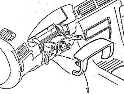
17.5. Pry up the cover 1 on the instrument panel from the side and then remove it
6. Remove the steering column cover by unscrewing the corresponding mounting bolts.
7. Unscrew bolts 1, 3, 5-7 and remove the upper 4 and lower 2 covers of the steering column switch block (see illustration).
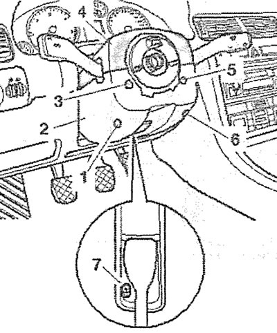
17.7. Unscrew bolts 1, 3, 5-7 and remove the upper 4 and lower 2 covers of the steering column switch block
8. Disconnect plugs 1 and 2 (see illustration).
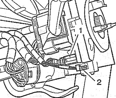
17.8. Disconnect plugs 1 and 2
9. Make sure that the hole (see arrow 1 in illustration 17.9) the yellow mark is visible on the contact ring, and both marks (see arrows in illustration 17.9) on the body the rings are in line. Fix the contact ring in this position with tape (see arrow in illustration 17.9a).
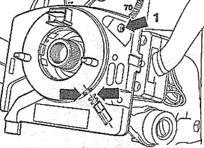
17.9. Make sure that there is a hole (see arrow 1) the yellow mark is visible on the contact ring, and both marks (see arrows) on the body the rings are in line |
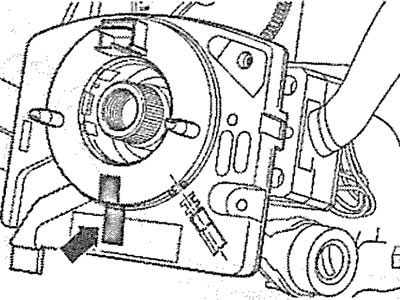
17.9a. Fix the contact ring in this position with tape (see arrow) |
10. Loosen bolt 2 of the steering column switch clamp so that they can be moved easily enough (see illustration).

17.10. Loosen bolt 2 of the clamp securing the steering column switches so that they can be moved easily enough
11. Disconnect plugs 1, 3 and 4 (see illustration 17.10), and then remove the switches from the steering shaft.
Installation
The installation of the steering column switches is carried out in the reverse order of removal.
12. Align the steering column switch 2 and the lower part 3 of the steering column cover so that the distance "a" from the steering wheel is 3 mm. In this position, tighten the bolt 1 of the switch mounting clamp (see illustration).
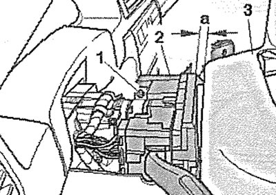
17.12. Align the steering column switch 2 and the lower part 3 of the steering column cover so that the distance "a" from the steering wheel is 3 mm. In this position, tighten the bolt 1 of the switch mounting clamp