
Table of contents: Collapse ↓ Convergence ↓
Collapse
1. Give the nut (And in the illustration) bolt connection between the wheel bearing housing and the tie rod and adjust the camber by turning bolt (B).
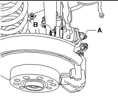
25.1. Camber adjustment
2. The maximum allowable turning angle is 90° in each direction.
3. Tighten the new nut (A) and check the camber again.
Convergence
4. Remove the casing (1 in the illustration) bottoms in the front part of the trapezoidal thrust.
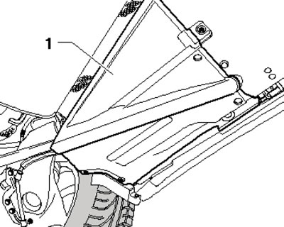
25.4. Bottom casing
5. Give the nut (With in the illustration) bolted connection between trapezoidal rod (inner front) and subframe. Adjust toe-in by turning the eccentric bolt (D) and tighten the new nut (C). The maximum allowable angle of rotation of the bolt is 90° in each direction.
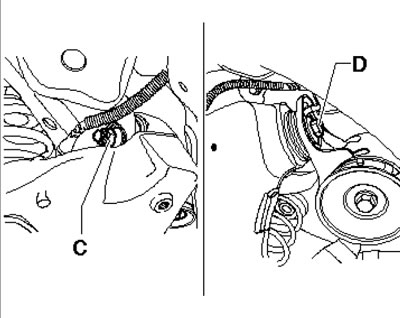
25.5. Convergence adjustment
6. Check the convergence again and, if necessary, repeat the adjustment.
(The original version of the article is posted on the website AUDIMANUAL.ru)