
External door handle
Removal
1. Raise the sliding door window completely. Then carefully remove the door trim panel and water-deflecting membrane as described in paragraph 17.
2. Remove the window lift carriage components - see paragraph 21.
3. Turn the locking element and remove it from the back of the handle and the lock cylinder (fig. 20.3, a, b).
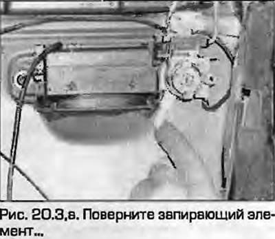 |
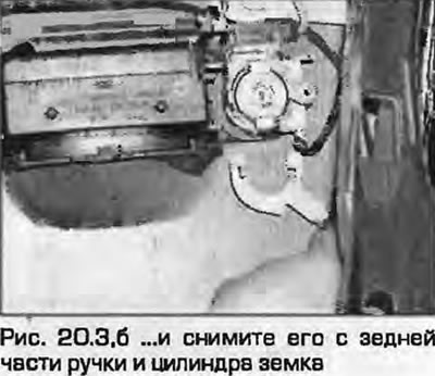 |
4. Loosen the mounting screw and remove the handle assembly from the door (fig. 20.4, a, 6), leaving the lock body in place.
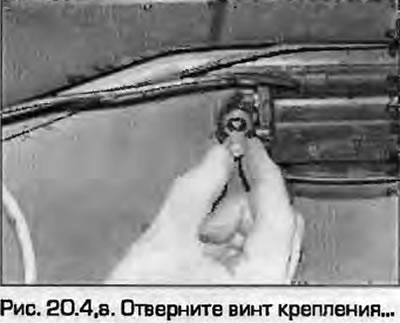 |
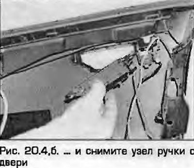 |
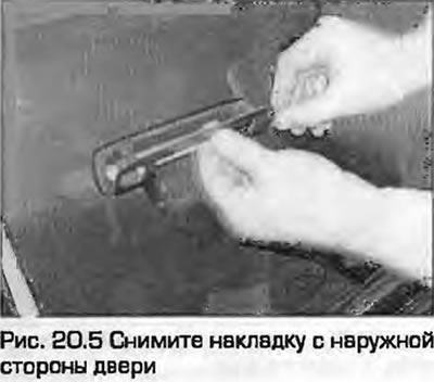
5. Remove the trim from the outside of the door (Fig. 20.5).
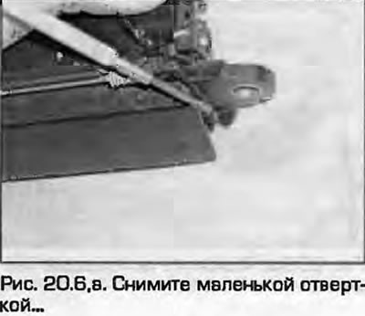
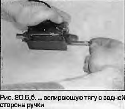
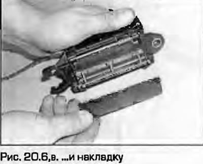
6. If necessary, use a small screwdriver to remove the locking rod from the back of the handle and the cover plate (fig. 20.6, a-c).
 |
 |
Installation
7. Installation - reverse procedure.
Lock cylinder
Removal
8. Remove the outside door handle as described above.
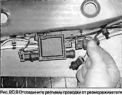
9. If provided, trace the wiring to the central locking switch and/or defroster element, from the rear of the lock cylinder housing to the wiring harness and disconnect the connectors (Fig. 20.9).
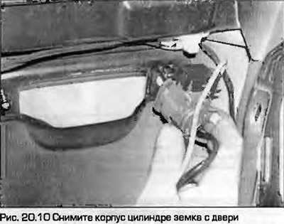
10. Remove the lock cylinder housing from the door (fig. 20.10).
11. To remove the lock cylinder from the housing, insert the key, remove the retainer from the back of the cylinder. Remove the drive plate and spring, rotate the cylinder 180° and remove it.
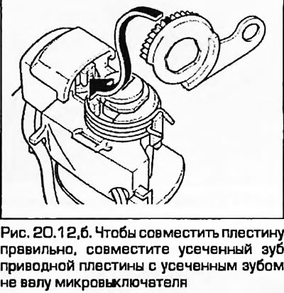
12. To install the new cylinder, insert it into the housing and turn it to the left with the key. Install the spring, drive plate and retainer. To align the plate correctly, align the truncated tooth of the drive plate with the truncated tooth on the microswitch shaft (fig. 20.12, a, b).
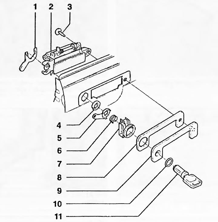
Fig. 20.12, a. Details of the handle and lock: 1. Shut-off element; 2. Pen; 3. Screw; 4. Retainer; 5. Drive plate; 6. Spring; 7. Body; 8. Plate; 9. Overlay; 10. Compaction; 11. Lock cylinder with key
Interior door handle
13. Remove the door trim panel and water-deflecting membrane as described in paragraph 17.
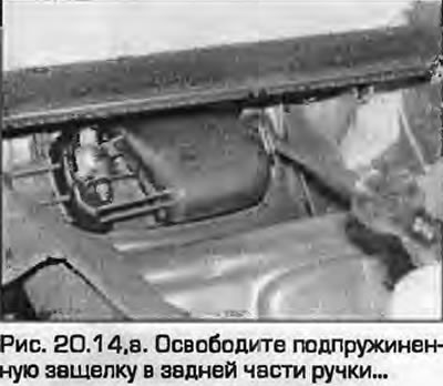
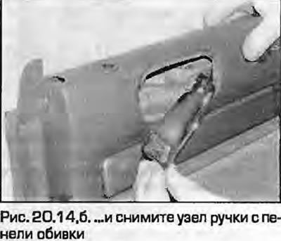
14. Release the spring-loaded latch at the rear of the handle, then remove the handle assembly from the trim panel (fig. 20.14, a, b).
 |
 |
15. Installation - reverse procedure.
(The original source of the article can be found on the website «audimanual.ru»)