
Repair Chevrolet Repair Toyota Repair Honda Repair AvtoVAZ Repair Mercedes-Benz Repair BMW Repair Opel
Home  |  Contacts  |  Sitemap  |    
English Русский
Български
Беларускі
Український
Српски
Hrvatski
Română
Polski
Slovenský
Magyar
AudiManual.ru


  • AUDI 80
  • AUDI 100
  • AUDI A3
  • AUDI A4
  • AUDI A6
  • AUDI A8
  • AUDI Q
  • OTHER
  • ARTICLES
Q7 Typ 4L (2005-2015, diesel) Q5 Type 8R (2008-2017)

Electrical, electronic components and their location (Audi Q5-8R)

  • Home
  • Audi Q
  • Q5 Type 8R (2008-2017)
  • Transmission
  • Automatic gearbox 0B5
  • Electrical, electronic components and their location
            0
Table of contents: Diagnostic connector ↓ Mechatronics for dual clutch gearbox… ↓

Diagnostic connector


Installation location: The diagnostic connector for the diagnostic complex is located in the footwell on the driver's side. Before troubleshooting, the cause should be determined precisely using the tester in the Guided Fault Finding, Self-Diagnostics and Measuring Equipment modes.
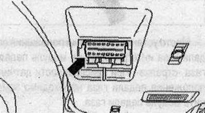
Installation location: The diagnostic connector for the diagnostic complex is located in the…


Mechatronics for dual clutch gearbox "J743", valves, sensors and gearbox input speed sensor
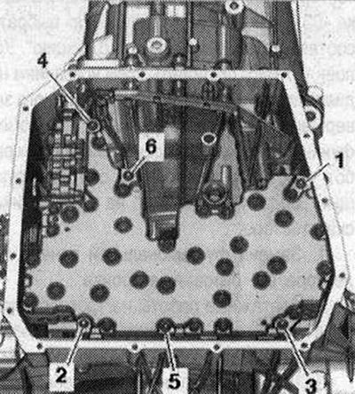


Mechatronics for dual clutch gearbox «J743», valves, sensors and gearbox input speed sensor


Location: Mechatronic gearbox with twin-disc clutch "J743" is screwed at the bottom of the gearbox housing and covered by the gearbox oil pan. Mechatronic combines hydraulic and electronic control units, sensors, and actuators into a specific single system. All elements are checked by means of self-diagnosis.
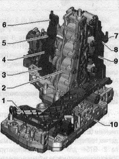


Overview of gear shifter, temperature sensor Mechatronics 1. Printed circuit board 1; 2. Fork…

Overview of gear shifter, temperature sensor Mechatronics 1. Printed circuit board 1; 2. Fork hydraulic valve module; 3. Speed sensor 1 fork hydraulic drive valves "G487" fork hydraulic drive valves 2-R; 4. Speed sensor 2 valves of hydraulic drive fork "G488" valves of hydraulic drive fork 1-3; 5. Speed sensor 3 valves of hydraulic drive of fork "G489" valves of hydraulic drive of fork 7-5; 6. Speed sensor 4 valves of hydraulic drive of fork "G490" valves of hydraulic drive of fork 4-6; 7. Clutch temperature sensor "G509"; 8. Sensor 3 of the speed of the input shaft of the gearbox "G641" of the speed of the input shaft of the gearbox; 9. Printed circuit board 2; 10. Electro-hydraulic control unit


PCB 1 and PCB 2 can be removed and installed separately.
The article was checked by auto expert Timur Bazhenov
This article is available at russian, bulgarian, belarusian, ukrainian, serbian, croatian, romanian, polish, slovak, hungarian

Share information:
Previous articles
Audi Q Q5 Type 8R: Automatic gearbox 0B5
Next articles

Replacing the drive shaft ball bearing
Removal the double clutch
Removal the flywheel
Flywheel and dual clutch
Mechatronic plug connectors and sensor modules
Guided functions on the control panel
Gear shift mechanism
Checking the gear shift mechanism


Similar articles on other Audi car models:
Electrical diagram of the instrument panel, tachometer,… Audi 80 B4 (1991-1996)
Throttle Cable and Throttle Pedal Components — Removal and… Audi 100 C3 (1982-1990, diesel)
Diagnostics of faults in vehicle components and systems Audi A3 Type 8L (1996-2003)
Electrical, electronic components and their location Audi A4 B8 (2007-2015)
Electronic Stability Program (ESP) Audi A6 C5 (1997-2004)
Checking the electrical wiring Audi A8 D2 (1994-2002)
Air filter parts and components Audi A2 (1999-2005)
Link to this page in different formats


Visitor comments

No comments yet


How much will 44 + 19 =


Q7 4L(2005-2015, diesel) 
  • General information
  • Operating instructions
  • Maintenance
  • Power unit
  • Diesels 3.0 l (BUG, BUN, CAS)
  • Diesels 3.0 l (CATA, CCMA)
  • Diesels 3.0 l (CJGA/CJGC)
  • Diesels 4.2 l (BTR, CCFA/CCFC)
  • Cooling system
  • Fuel and exhaust system
  • Engine management system
  • Starting and charging
  • Transmission
  • Automatic gearbox
  • Drive shafts
  • Chassis
  • Brake system
  • Front suspension
  • Rear suspension
  • Steering system
  • Body
  • Air conditioner
  • Exterior
  • Interior
  • Electrical equipment
  • Equipment and devices
  • Electrical circuits
 
Q5 8R(2008-2017) 
  • General information
  • User manual
  • Power unit
  • Petrol engine 2.0 l
  • Petrol engine 3.2 l
  • Fuel system (petrol)
  • Diesel 2.0 liter (CA)
  • Diesel 2.0 liter (CG/CJ/CM)
  • Diesel engine 3.0 l
  • Fuel system (diesel)
  • Transmission
  • Manual gearbox 0B1
  • Manual gearbox 0B2
  • Automatic gearbox 0B5
  • Automatic gearbox 0B6
  • Chassis
  • Front suspension
  • Rear suspension
  • Brake system
  • Steering
  • Body
  • Exterior
  • Interior
  • Doors, locks and windows
  • Safety system
  • Ventilation and heating
  • Electrical equipment
  • Power devices
  • Equipment and devices
  • Lighting and alarm
  • Audio system
  • Electrical circuits
 
AudiManual.ru © 2017-2026 · Mobile version · Feedback · Sitemap: EN BG BY UA RS HR RO PL SK HU · Site search · News and articles
80 B2 · 80 B3 petrol · 80 B3 · 80 B4 · 100 C3 diesel · 100 C3 petrol · 100 C3 · 100 C4 petrol · 100 C4 · A3 Type 8L · A4 B5 petrol · A4 B5 · A4 B6 petrol · A4 B6 · A4 B7 · A4 B8 · A6 C4 · A6 C5 · A6 C5 Allroad · A8 D2 · Q5 Type 8R · Q7 Typ 4L · Audi A2 ·
This site uses cookies 🍪. Click the button to accept this fact.